 Honda CBR650 - Service manual > PGM-FI troubleshooting information/symptom troubleshooting
PGM-FI troubleshooting information
GENERAL TROUBLESHOOTING
Intermittent Failure
The term "intermittent failure" means a system may have had a failure, but it checks OK now. If the MIL does not come on, check for poor contact or loose pins at all connectors related to the circuit that of the troubleshooting. If the MIL was on, but then went out, the original problem may be intermittent.
Opens and Shorts
"Opens" and "Shorts" are common electrical terms. An open is a break in a wire or at a connection. A short is an accidental connection of a wire to ground or to another wire. In simple electronics, this usually means something will not work at all. With ECM this can mean something may work, but not the way it's supposed to.
If the MIL has come on
Refer to DTC READOUT.
If the MIL did not stay on
If the MIL did not stay on, but there is a driveability problem, do the SYMPTOM TROUBLESHOOTING.
SYSTEM DESCRIPTION
SELF-DIAGNOSIS SYSTEM
The PGM-FI system is equipped with the self-diagnostic system. When any abnormality occurs in the system, the ECM turns on the MIL and stores a DTC in its erasable memory.
FAIL-SAFE FUNCTION
The PGM-FI system is provided with a fail-safe function to secure a minimum running capability even when there is trouble in the system. When any abnormality is detected by the self-diagnosis function, running capability is maintained by pre-programed value in the simulated program map. When any abnormality is detected in the injector, the fail-safe function stops the engine to protect it from damage.
DTC
- The DTC is composed of a main code and a sub code and it is displayed as
a hyphenated number when retrieved from the ECM with the MCS.
The digits in front of the hyphen are the main code, they indicate the component of function failure.
The digits behind the hyphen are the sub code, they detail the specific symptom of the component or function failure.
For example, in the case of the TP sensor:
- DTC 08-1 = (TP sensor voltage) - (lower than the specified value)
- DTC 08-2 = (TP sensor voltage) - (higher than the specified value)
- The MAP, ECT, TP and IAT sensor diagnosis will be made according to the
voltage output of the affected sensor.
If a failure occurs, the ECM determines the Function Failure, compares the sensor voltage output to the standard value, and then outputs the corresponding DTC to the MCS.
For example:
- If the output voltage line on the MAP sensor is opened, the ECM detects the output voltage is about 5 V, then the DTC 1-2 (MAP sensor circuit high voltage) will be displayed.
- If the input voltage line on the TP sensor is opened, the ECM detects the output voltage is 0 V, then the DTC 8-1 (TP sensor circuit low voltage) will be displayed.
MIL BLINK PATTERN
- If the MCS is not available, DTC can be read from the ECM memory by the MIL blink pattern.
- The number of MIL blinks is the equivalent to the main code of the DTC (the sub code cannot be displayed by the MIL).
- The MIL will blink the current DTC, in case the ECM detects the problem
at present, when the ignition switch is turned ON with the engine stop
switch "
 "
or idling with the sidestand down. The MIL will stay ON when the engine
speed is over 1,800 min-1 (rpm) or with the sidestand up.
"
or idling with the sidestand down. The MIL will stay ON when the engine
speed is over 1,800 min-1 (rpm) or with the sidestand up. - The MIL has two types of blinks, a long blink and short blink. The long blinking lasts for 1.3 seconds, the short blinking lasts for 0.3 seconds. One long blink is the equivalent of ten short blinks. For example, when two long blinks are followed by nine short blinks, the DTC is 29 (two long blinks = 20 blinks, plus nine short blinks).
- When the ECM stores more than one DTC, the MIL will indicate them by blinking in the order from the lowest number to highest number.
MIL CHECK
When the ignition switch is turned ON with the engine stop switch "",
the MIL will stay on for a few seconds, then go off. If the MIL does not come on
or stays on, inspect the MIL circuit.
CURRENT DTC/STORED DTC
The DTC is indicated in two ways according to the failure status.
- In case the ECM detects the problem at present, the MIL will start blinking as its DTC. It is possible to read out the MIL blink pattern as the current DTC.
- In case the ECM does not detect any problem at present but has a problem stored in its memory, the MIL will not blink. If it is necessary to retrieve the past problem, read out the stored DTC by following the DTC Readout procedure.
MCS INFORMATION
- The MCS can read out the DTC, stored data, current data and other ECM condition.
How to connect the MCS
Remove the seat.
Turn the ignition switch OFF.
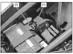
Release the DLC [1] from the stay [2], then remove the dummy connector from the DLC.
Connect the MCS to the DLC.
Turn the ignition switch ON with the engine stop switch " "
and check the DTC and stored data.
"
and check the DTC and stored data.
NOTE:
- Stored data indicates the engine conditions when the first malfunction was detected.
DTC READOUT
Current DTC
Turn the ignition switch ON with the engine stop switch ""
and check the MIL.
Start the engine and check the MIL. If the engine will not start, turn the starter motor for more than 10 seconds and check that the MIL blinks.
If the MIL blinks, connect the MCS to the DLC.
Read the DTC, stored data and follow the DTC index.
- If the MIL does not blink, the system is normal at present. If you wish to read the stored DTC, connect the MCS to the DLC.
- If the MCS is not available, note how many times the MIL blinks and follow the DTC index. If you wish to read the stored DTC, perform the following.
Reading stored DTC with the MIL
Remove the seat.
Turn the ignition switch OFF.
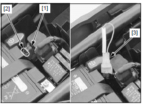
Release the DLC [1] from the stay [2], then remove the dummy connector from the DLC.
Short the DLC terminals using the special tool.
TOOL:
[3] SCS connector 070PZ-ZY30100
CONNECTION: Brown - Green
Turn the ignition switch ON with the engine stop switch "",
read the MIL blinks and refer to the DTC index.
- If the ECM has stored DTC in its memory, the MIL will illuminate 0.3 seconds and go off, then start blinking as its DTC when you turn the ignition switch ON.
- If the ECM has no stored DTC, the MIL will illuminate and stay on when you turn the ignition switch ON.
ERASING STORED DTC
NOTE:
- The stored DTC can not be erased by simply disconnecting the battery negative cable.
Erase the DTC with the MCS while the engine is stopped.
How to erase the DTC without MCS
1. Connect the SCS connector to the DLC.
2. Turn the ignition switch ON with the engine stop switch "".
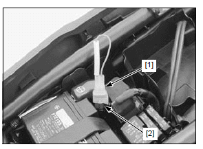
3. Disconnect the SCS connector [1] from the DLC [2].
Connect the SCS connector to the DLC again while the MIL stays ON within 5 seconds (reset receiving pattern).
4. The stored DTC is erased if the MIL goes off and starts blinking (successful pattern).
- The DLC must be jumped while the MIL lights. If not, the MIL will go off and stay on (unsuccessful pattern). In that case, turn the ignition switch OFF and try again.
- Note that the self-diagnostic memory cannot be erased if the ignition switch is turned OFF before the MIL starts blinking.
CIRCUIT INSPECTION
INSPECTION AT ECM CONNECTOR
- Always clean around and keep any foreign material away from the ECM 33P (Black) and 33P (Gray) connectors before disconnecting it.
- A faulty PGM-FI system is often related to poorly connected or corroded terminals. Check those connections before proceeding.
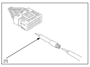
- In testing at ECM 33P (Black) and 33P (Gray) connector terminal (wire harness side), always use the test probe. Insert the test probe into the connector terminal, then attach the digital multimeter probe to the test probe.
TOOL:
[1] Test probe 07ZAJ-RDJA110
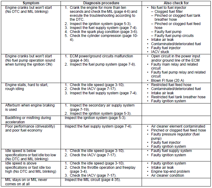
PGM-FI symptom troubleshooting
When the motorcycle has one of these symptoms, check the DTC or MIL blinking, refer to the DTC index and begin the appropriate troubleshooting procedure. If there are no DTC stored in the ECM memory, do the diagnostic procedure for the symptom, in sequence listed below, until you find cause.
See also:
 Honda CBR650 - Service manual > System location/system diagram/service information
System location BANK ANGLE SENSOR IACV IAT SENSOR MAP SENSOR ECM DLC CKP SENSOR O2 SENSOR VS SENSOR ECT SENSOR FUEL INJECTOR TP SENSOR
Honda CBR650 - Service manual > DTC index
NOTE: If the MCS is not used, perform all of the inspection on the corresponding main code (digits in front of hyphen) of the DTC.
 Rider's Manual BMW R 1250 GS GSA
 Owner's Manual Harley-Davidson Sportster XL1200X Forty-Eight
 Owner's Manual Honda CBR650R
 Service manual Honda CBR650
 Owner's Manual Honda PCX125
 Owner's Manual Kawasaki Z1000SX
 Service manual Kawasaki Z1000SX
 Owner's Manual Lexmoto Echo
 Owner's Manual Royal Enfield Interceptor 650
 Service manual Royal Enfield Interceptor 650
 Owner's Manual Yamaha MT-07