 Honda CBR650 - Service manual > DTC index
NOTE:
- If the MCS is not used, perform all of the inspection on the corresponding main code (digits in front of hyphen) of the DTC.
DTC troubleshooting
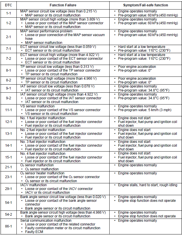
DTC 1 (MAP SENSOR)
Probable cause
- Open circuit in Yellow/red or Green/yellow wire between the MAP sensor and ECM
- Open or short circuit in Violet/red wire between the MAP sensor and ECM
- Faulty MAP sensor
- Faulty ECM
DTC 1-1 (MAP SENSOR LOW VOLTAGE)
1. MAP Sensor System Inspection
Check the MAP sensor with the MCS.
Is about 0 V indicated?
YES - GO TO STEP 2.
NO - Intermittent failure
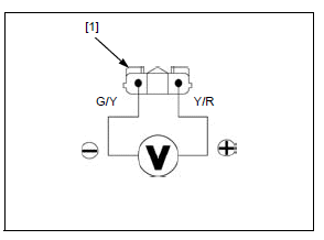
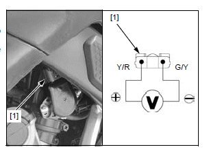
2. MAP Sensor Input Voltage Inspection
Turn the ignition switch OFF.
Disconnect the MAP sensor 3P (Black) connector.
Turn the ignition switch ON with the engine stop switch " ".
".
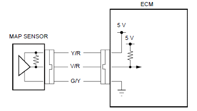
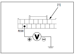
Measure the voltage between the wire harness side MAP sensor 3P (Black) connector [1] terminals.
CONNECTION: Yellow/red (+) - Green/yellow (-)
STANDARD: 4.75 - 5.25 V
Is the voltage within standard value?
YES - GO TO STEP 4.
NO - GO TO STEP 3.
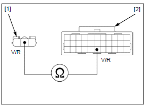
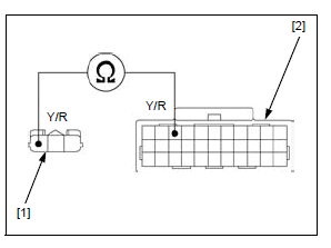
3. MAP Sensor Input Line Open Circuit Inspection
Turn the ignition switch OFF.
Disconnect the ECM 33P (Black) connector.
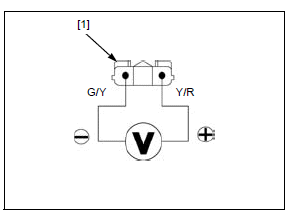
Check for continuity between the wire harness side MAP sensor 3P (Black) connector [1] and ECM 33P (Black) connector [2] terminals.
TOOL:
Test probe 07ZAJ-RDJA110
CONNECTION: Yellow/red - Yellow/red
Is there continuity?
YES - Replace the ECM with a known good one, and recheck.
NO - Open circuit in Yellow/red wire
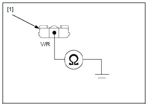
4. MAP Sensor Signal Line Short Circuit Inspection
Turn the ignition switch OFF.
Disconnect the ECM 33P (Black) connector.
Check for continuity between MAP sensor 3P (Black) connector [1] terminal and ground.
CONNECTION: Violet/red - Ground
Is there continuity?
YES - Short circuit in Violet/red wire
NO - GO TO STEP 5.
5. MAP Sensor Inspection
Replace the MAP sensor with a known good one.
Connect the ECM 33P (Black) connector.
Erase the DTC.
Check the MAP sensor with the MCS.
Is DTC 1-1 indicated?
YES - Replace the ECM with a known good one, and recheck.
NO - Faulty original MAP sensor
DTC 1-2 (MAP SENSOR HIGH VOLTAGE)
- Before starting the inspection, check for loose or poor contact on the MAP sensor 3P (Black) and ECM 33P (Gray) connectors, and recheck the DTC.
1. MAP Sensor System Inspection.
Check the MAP sensor with the MCS.
Is about 5 V indicated?
YES - GO TO STEP 2.
NO - Intermittent failure
2. MAP Sensor Input Voltage Inspection.
Turn the ignition switch OFF.
Disconnect the MAP sensor 3P (Black) connector.
Turn the ignition switch ON with the engine stop switch "".
Measure the voltage between the wire harness side MAP sensor 3P (Black) connector [1] terminals.
CONNECTION: Yellow/red (+) - Green/yellow (-)
STANDARD: 4.75 - 5.25 V
Is the voltage within standard value?
YES - GO TO STEP 3.
NO - Open circuit in Green/yellow wire
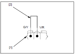
3. MAP Sensor System Inspection with Jumper Wire.
Turn the ignition switch OFF.
Connect the wire harness side MAP sensor 3P (Black) connector [1] terminals with a jumper wire [2].
CONNECTION: Violet/red - Green/yellow
Check the MAP sensor with the MCS.
Is about 0 V indicated?
YES - Faulty MAP sensor
NO - GO TO STEP 4.
4. MAP Sensor Signal Line Open Circuit Inspection.
Turn the ignition switch OFF.
Disconnect the ECM 33P (Gray) connector.
Check for continuity between the wire harness side MAP sensor 3P (Black) connector [1] and ECM 33P (Gray) connector [2] terminals.
TOOL: Test probe 07ZAJ-RDJA110
CONNECTION: Violet/red - Violet/red
Is there continuity?
YES - Replace the ECM with a known good one, and recheck.
NO - Open circuit in Violet/red wire
DTC 2 (MAP SENSOR)
Probable cause
- Loose or poor connection of the MAP sensor vacuum hose
- Faulty MAP sensor
- Faulty ECM
DTC 2-1 (MAP SENSOR)
1. MAP Sensor System Inspection
Start the engine and check the MAP sensor with the MCS at idle speed.
Is the reading changed?
YES - Intermittent failure
NO - GO TO STEP 2.
2. Manifold Absolute Pressure Test
Stop the engine.
Lift the fuel tank and support it.
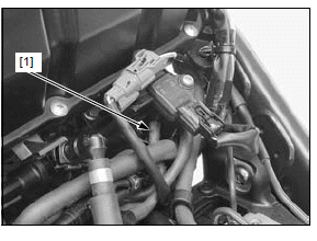
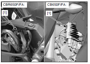
Check for connection and installation of the MAP sensor vacuum hose [1].
Is the MAP sensor vacuum hose connection correct?
YES - GO TO STEP 3.
NO - Correct the hose installation.
3. MAP Sensor System Inspection.
Replace the MAP sensor with a known good one.
Start the engine.
Check the MAP sensor with the MCS at idle speed.
Is the reading changed?
YES - Faulty original MAP sensor
NO - Replace the ECM with a known good one and recheck.
DTC 7 (ECT SENSOR)
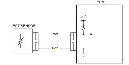
Probable cause
- Open or short circuit in Pink/white wire between the ECT sensor and ECM
- Open circuit in Green/yellow wire between the ECT sensor and ECM
- Faulty ECT sensor
- Faulty ECM
DTC 7-1 (ECT SENSOR LOW VOLTAGE)
1. ECT Sensor System Inspection
Check the ECT sensor with the MCS.
Is about 0 V indicated?
YES - GO TO STEP 2.
NO - Intermittent failure
2. ECT Sensor System Inspection with Connector Disconnected
Turn the ignition switch OFF.
Disconnect the ECT sensor 2P (Blue) connector.
Check the ECT sensor with the MCS.
Is about 0 V indicated?
YES - GO TO STEP 3.
NO - Faulty ECT sensor
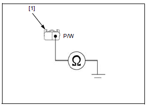
3. ECT Sensor Output Line Short Circuit Inspection
Turn the ignition switch OFF.
Disconnect the ECM 33P (Gray) connector.
Check for continuity between the wire harness side ECT sensor 2P (Blue) connector [1] terminal and ground.
CONNECTION: Pink/white - Ground
Is there continuity?
YES - Short circuit in Pink/white wire
NO - Replace the ECM with a known good one, and recheck.
DTC 7-2 (ECT SENSOR HIGH VOLTAGE)
- Before starting the inspection, check for loose or poor contact on the ECT sensor 2P (Blue), ECM 33P (Black) and 33P (Gray) connectors, and recheck the DTC.
1. ECT Sensor System Inspection
Check the ECT sensor with the MCS.
Is about 5 V indicated?
YES - GO TO STEP 2.
NO - Intermittent failure
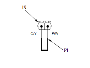
2. ECT Sensor System Inspection with Jumper Wire
Turn the ignition switch OFF.
Disconnect the ECT sensor 2P (Blue) connector.
Connect the wire harness side ECT sensor 2P (Blue) connector [1] terminals with a jumper wire [2].
CONNECTION: Pink/white - Green/yellow
Check the ECT sensor with the MCS.
Is about 0 V indicated?
YES - GO TO STEP 4.
NO - GO TO STEP 3.
3. ECT Sensor Line Open Circuit Inspection
Turn the ignition switch OFF.
Disconnect the ECM 33P (Black) and 33P (Gray) connectors.
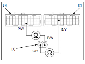
Check for continuity between the wire harness side ECT sensor 2P (Blue) connector [1] and ECM 33P (Black) [2] and 33P (Gray) [3] connector terminals.
TOOL: Test probe 07ZAJ-RDJA110
CONNECTION:
Pink/white - Pink/white
Green/yellow - Green/yellow
Is there continuity?
YES - Replace the ECM with a known good one, and recheck.
NO -
- Open circuit in Pink/white wire
- Open circuit in Green/yellow wire
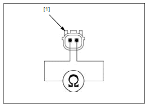
4. ECT Sensor Resistance Inspection
Turn the ignition switch OFF.
Remove the ECT sensor.
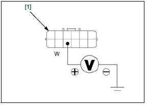
Measure the resistance between the 2P connector terminals of the ECT sensor [1].
STANDARD: 1.0 - 1.3 kΩ (40ºC/104ºF)
Is the resistance within standard value?
YES - Replace the ECM with a known good one, and recheck.
NO - Faulty ECT sensor
DTC 8 (TP SENSOR)
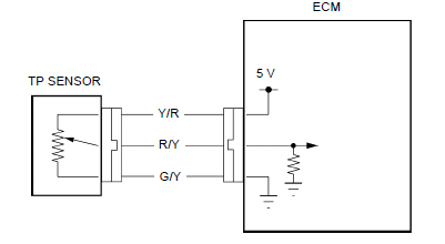
Probable cause
- Open circuit in Yellow/red or Green/yellow wire between the TP sensor and ECM
- Open or short circuit in Red/yellow wire between the TP sensor and ECM
- Short circuit between Yellow/red and Red/yellow wires
- Faulty TP sensor
- Faulty ECM
DTC 8-1 (TP SENSOR LOW VOLTAGE)
- Before starting the inspection, check for loose or poor contact on the TP sensor 3P (Blue), ECM 33P (Black) and 33P (Gray) connectors, and recheck the DTC.
1. TP Sensor System Inspection
Check the TP sensor with the MCS with the throttle fully closed.
Is about 0 V indicated?
YES - GO TO STEP 2.
NO - Intermittent failure
2. TP Sensor Input Voltage Inspection
Turn the ignition switch OFF.
Disconnect the TP sensor 3P (Blue) connector [1].
Turn the ignition switch ON with the engine stop switch "".
Measure the voltage between the wire harness side TP sensor 3P (Blue) connector terminals.
CONNECTION: Yellow/red (+) - Green/yellow (-)
STANDARD: 4.75 - 5.25 V
Is the voltage within standard value?
YES - GO TO STEP 4.
NO - GO TO STEP 3.
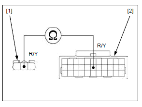
3. TP Sensor Input Line Open Circuit Inspection
Turn the ignition switch OFF.
Disconnect the ECM 33P (Black) connector.
Check for continuity between the wire harness side TP sensor 3P (Blue) connector [1] and ECM 33P (Black) connector [2] terminals.
TOOL:
Test probe 07ZAJ-RDJA110
CONNECTION: Yellow/red - Yellow/red
Is there continuity?
YES - Replace the ECM with a known good one, and recheck.
NO - Open circuit in Yellow/red wire
4. TP Sensor Signal Line Open Circuit Inspection
Turn the ignition switch OFF.
Disconnect the ECM 33P (Gray) connector.
Check for continuity between the wire harness side TP sensor 3P (Blue) connector [1] and ECM 33P (Gray) connector [2] terminals.
TOOL:
Test probe 07ZAJ-RDJA110
CONNECTION: Red/yellow - Red/yellow
Is there continuity?
YES - GO TO STEP 5.
NO - Open circuit in Red/yellow wire
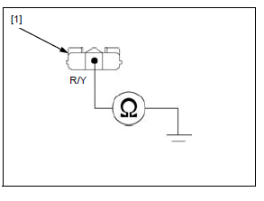
5. TP Sensor Signal Line Short Circuit Inspection
Check for continuity between the wire harness side TP sensor 3P (Blue) connector [1] terminal and ground.
CONNECTION: Red/yellow - Ground
Is there continuity?
YES - Short circuit in Red/yellow wire
NO - GO TO STEP 6.
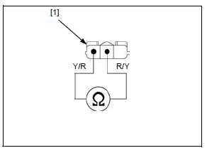
6. TP Sensor Inspection
Replace the throttle body (TP sensor) with a known good one.
Connect the ECM 33P (Gray) connector.
Erase the DTC.
Check the TP sensor with the MCS.
Is DTC 8-1 indicated?
YES - Replace the ECM with a known good one, and recheck.
NO - Faulty original TP sensor
DTC 8-2 (TP SENSOR HIGH VOLTAGE)
1. TP Sensor System Inspection
Check the TP sensor with the MCS.
Is about 5 V indicated?
YES - GO TO STEP 3.
NO - GO TO STEP 2.
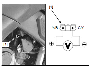
2. TP Sensor System Inspection with throttle operated
Check that the TP sensor voltage increases continuously when moving the throttle from fully closed position to fully opened position using the data list menu of the MCS.
Is the voltage increase continuously?
YES - Intermittent failure
NO - Faulty TP sensor
3. TP Sensor Input Voltage Inspection
Turn the ignition switch OFF.
Disconnect the TP sensor 3P (Blue) connector [1].
Turn the ignition switch ON with the engine stop switch "".
Measure the voltage between the wire harness side TP sensor 3P (Blue) connector terminals.
CONNECTION: Yellow/red (+) - Green/yellow (-)
STANDARD: 4.75 - 5.25 V
Is the voltage within standard value?
YES - GO TO STEP 4.
NO - Open circuit in Green/yellow wire
4. TP Sensor Line Short Circuit Inspection
Turn the ignition switch OFF.
Disconnect the ECM 33P (Black) and 33P (Gray) connectors.
Check for continuity between the wire harness side TP sensor 3P (Blue) connector [1] terminals.
CONNECTION: Yellow/red - Red/yellow
Is there continuity?
YES - Short circuit between Yellow/red and Red/ yellow wires
NO - GO TO STEP 5.
5. TP Sensor Inspection
Replace the throttle body (TP sensor) with a known good one.
Connect the ECM 33P connectors.
Erase the DTC.
Check the TP sensor with the MCS.
Is DTC 8-2 indicated?
YES - Replace the ECM with a known good one, and recheck.
NO - Faulty original TP sensor
DTC 9 (IAT SENSOR)
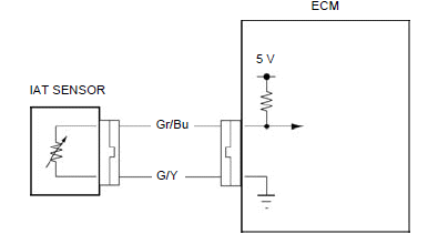
Probable cause
- Open or short circuit in Gray/blue wire between the IAT sensor and ECM
- Open circuit in Green/yellow wire between the IAT sensor and ECM
- Faulty IAT sensor
- Faulty ECM
DTC 9-1 (IAT SENSOR LOW VOLTAGE)
1. IAT Sensor System Inspection
Check the IAT sensor with the MCS.
Is about 0 V indicated?
YES - GO TO STEP 2.
NO - Intermittent failure
2. IAT Sensor System Inspection with Connector Disconnected
Turn the ignition switch OFF.
Disconnect the IAT sensor 2P (Black) connector.
Check the IAT sensor with the MCS.
Is about 0 V indicated?
YES - GO TO STEP 3.
NO - Faulty IAT sensor
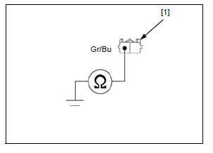
3. IAT Sensor Output Line Short Circuit Inspection
Turn the ignition switch OFF.
Disconnect the ECM 33P (Gray) connector.
Check for continuity between the wire harness side IAT sensor 2P (Black) connector [1] terminal and ground.
CONNECTION: Gray/blue - Ground
Is there continuity?
YES - Short circuit in Gray/blue wire
NO - Replace the ECM with a known good one, and recheck.
DTC 9-2 (IAT SENSOR HIGH VOLTAGE)
- Before starting the inspection, check for loose or poor contact on the IAT sensor 2P (Black), ECM 33P (Black) and 33P (Gray) connectors, and recheck the DTC.
1. IAT Sensor System Inspection
Check the IAT sensor with the MCS.
Is about 5 V indicated?
YES - GO TO STEP 2.
NO - Intermittent failure
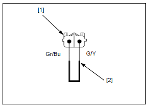
2. IAT Sensor System Inspection with Jumper Wire
Turn the ignition switch OFF.
Disconnect the IAT sensor 2P (Black) connector.
Connect the wire harness side IAT sensor 2P (Black) connector [1] terminals with a jumper wire [2].
CONNECTION: Gray/blue - Green/yellow
Check the IAT sensor with the MCS.
Is about 0 V indicated?
YES - Faulty IAT sensor
NO - GO TO STEP 3.
3. IAT Sensor Line Open Circuit Inspection
Turn the ignition switch OFF.
Disconnect the ECM 33P (Black) and 33P (Gray) connectors.
Check for continuity between the wire harness side IAT sensor 2P (Black) connector [1] and ECM 33P (Black) [2]/33P (Gray) [3] connector terminals.
TOOL:
Test probe 07ZAJ-RDJA110
CONNECTION:
Gray/blue - Gray/blue
Green/yellow - Green/yellow
Is there continuity?
YES - GO TO STEP 4.
NO -
- Open circuit in Gray/blue wire
- Open circuit in Green/yellow wire
4. IAT Sensor Resistance Inspection
Connect the IAT sensor 2P (Black) connector.
Measure the resistance between the wire harness side ECM 33P (Black) [1] and 33P (Gray) [2] connector terminals.
TOOL:
Test probe 07ZAJ-RDJA110
CONNECTION: Gray/blue - Green/yellow
STANDARD: 1 - 4 kΩ (20ºC/68ºF)
Is the resistance within standard value?
YES - Replace the ECM with a known good one, and recheck.
NO - Faulty IAT sensor
DTC 11 (VS SENSOR)
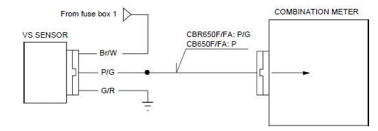
Probable cause
- Open circuit in Brown/white wire between the fuse box 1 and VS sensor
- Open circuit in Green/red wire between the VS sensor and ground
- Open or short circuit in Pink/green wire between the VS sensor and combination meter
- Faulty VS sensor
- Faulty combination meter
DTC 11-1 (VS SENSOR)
- Before starting the inspection, check for loose or poor contact on the VS sensor 3P (Black) and combination meter 16P (Gray) connectors, and recheck the DTC.
1. Recheck DTC
Erase the DTC.
Test-ride the motorcycle above 3,800 min-1 (rpm).
Stop the engine.
Check the VS sensor with the MCS.
Is DTC 11-1 indicated?
YES - GO TO STEP 2.
NO - Intermittent failure
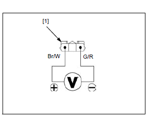
2. VS Sensor Input Voltage Inspection
Turn the ignition switch OFF.
Disconnect the VS sensor 3P (Black) connector.
Turn the ignition switch ON with the engine stop switch "".
Measure the voltage between the wire harness side VS sensor 3P (Black) connector [1] terminals.
CONNECTION: Brown/white (+) - Green/red (-)
YES - GO TO STEP 3.
NO -
- Open circuit in Brown/white wire
- Open circuit in Green/red wire
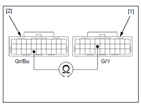
3. VS Sensor Signal Line Short Circuit Inspection
Turn the ignition switch OFF.
Check for continuity between the wire harness side VS sensor 3P (Black) connector [1] terminal and ground.
CONNECTION: Pink/green - Ground
Is there continuity?
YES - Short circuit in Pink/green wire
NO - GO TO STEP 4.
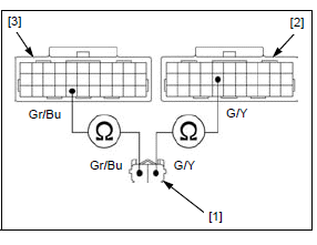
4. VS Sensor Signal Line Open Circuit Inspection
Disconnect the combination meter 16P (Gray) connector as the combination meter power/ground line inspection.
Check for continuity between the wire harness side VS sensor 3P (Black) connector [1] and combination meter 16P (Gray) connector [2] terminals.
TOOL:
Test probe 07ZAJ-RDJA110
CONNECTION:
CBR650F/FA: Pink/green - Pink/green
CB650F/FA: Pink/green - Pink
Is there continuity?
YES - GO TO STEP 5.
NO -
- CBR650F/FA: Open circuit in Pink/ green wire
- CB650F/FA: Open circuit in Pink/green or Pink wire
5. VS Sensor Inspection
Replace the VS sensor with a known good one.
Connect the combination meter 16P (Gray) connector.
Erase the DTC.
Test-ride the motorcycle above 3,800 min-1 (rpm).
Stop the engine.
Check the DTC with the MCS.
Is DTC 11-1 indicated?
YES - Replace the combination meter with a known good one, and recheck.
NO - Faulty original VS sensor
DTC 12 (No. 1 FUEL INJECTOR)/
DTC 13 (No. 2 FUEL INJECTOR)/
DTC 14 (No. 3 FUEL INJECTOR)/
DTC 15 (No. 4 FUEL INJECTOR)
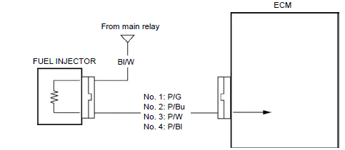
Probable cause
- Open circuit in Black/white wire between the main relay and fuel injector
- Open or short circuit in Pink/green (No. 1) or Pink/ blue (No. 2) or Pink/white (No. 3) or Pink/black (No.4) wire between the fuel injector and ECM
- Faulty fuel injector
- Faulty ECM
DTC 12-1 (No. 1 FUEL INJECTOR)/
DTC 13-1 (No. 2 FUEL INJECTOR)/
DTC 14-1 (No. 3 FUEL INJECTOR)/
DTC 15-1 (No. 4 FUEL INJECTOR)
- Before starting the inspection, check for loose or poor contact on the fuel injector 2P (Black) and ECM 33P (Black) connectors, and recheck the DTC.
1. Recheck DTC
Erase the DTC.
Start the engine and check the fuel injector with the MCS.
Is the DTC 12-1, 13-1, 14-1 or 15-1 indicated?
YES - GO TO STEP 2.
NO - Intermittent failure
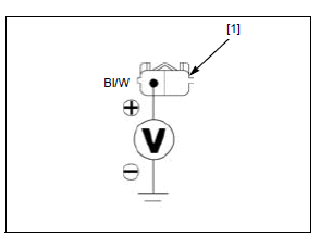
2. Fuel Injector Input Voltage Inspection
Turn the ignition switch OFF.
Lift the fuel tank and support it.
Disconnect the fuel injector 2P (Black) connector.
Turn the ignition switch ON with the engine stop switch "".
Measure the voltage between the wire harness side injector 2P (Black) connector [1] terminal and ground.
CONNECTION: Black/white (+) - Ground (-)
Is there battery voltage?
YES - GO TO STEP 3.
NO - Open circuit in Black/white wire
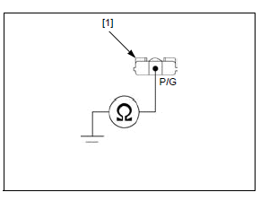
3. Fuel Injector Resistance Inspection
Turn the ignition switch OFF.
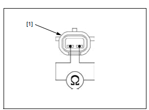
Measure the resistance between the 2P connector terminals of the fuel injector [1].
STANDARD: 11 - 13 Ω (20ºC/68ºF)
Is the resistance within standard value?
YES - GO TO STEP 4.
NO - Faulty fuel injector
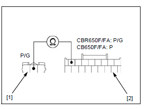
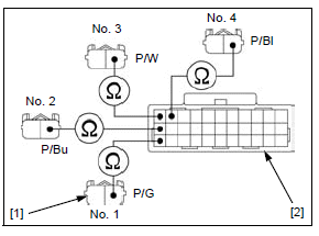
4. Fuel Injector Signal Line Open Circuit Inspection
Disconnect the ECM 33P (Black) connector.
Check for continuity between the wire harness side fuel injector 2P (Black) connector [1] and ECM 33P (Black) connector [2] terminals.
TOOL:
Test probe 07ZAJ-RDJA110
CONNECTION:
No. 1: Pink/green - Pink/green
No. 2: Pink/blue - Pink/blue
No. 3: Pink/white - Pink/white
No. 4: Pink/black - Pink/black
Is there continuity?
YES - GO TO STEP 5.
NO -
- Open circuit in Pink/green wire
- Open circuit in Pink/blue wire
- Open circuit in Pink/white wire
- Open circuit in Pink/black wire
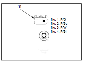
5. Fuel Injector Signal Line Short Circuit Inspection
Check for continuity between the wire harness side injector 2P (Black) connector [1] terminal and ground.
CONNECTION:
No. 1: Pink/green - Ground
No. 2: Pink/blue - Ground
No. 3: Pink/white - Ground
No. 4: Pink/black - Ground
Is there continuity?
YES -
- Short circuit in Pink/green wire
- Short circuit in Pink/blue wire
- Short circuit in Pink/white wire
- Short circuit in Pink/black wire
NO - Replace the ECM with a known good one, and recheck.
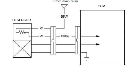
DTC 21 (O2 SENSOR)
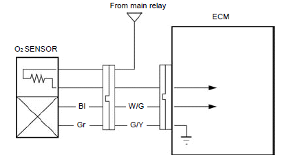
Probable cause
- Open or short circuit in White/green wire between the ECM and O2 sensor
- Open circuit in Green/yellow wire between the O2 sensor and ECM
- Faulty O2 sensor
- Faulty ECM
DTC 21-1 (O2 Sensor)
- Before starting the inspection, check for loose or poor contact on the O2 sensor 4P (Black), ECM 33P (Black) and 33P (Gray) connectors, and recheck the DTC.
1. Recheck DTC
Erase the DTC.
Start the engine and warm it up until the coolant temperature is 80ºC (176ºF).
Stop the engine.
Check the O2 sensor with the MCS.
Is the DTC 21-1 indicated?
YES - GO TO STEP 2.
NO - Intermittent failure
2. O2 Sensor Line Open Circuit Inspection
Turn the ignition switch OFF.
Disconnect the following:
- O2 sensor 4P (Black) connector.
- ECM 33P (Black)/33P (Gray) connectors.
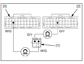
Check for continuity between the wire harness side O2 sensor 4P (Black) connector [1] and ECM 33P (Black) [2]/33P (Gray) [3] connector terminals.
TOOL:
Test probe 07ZAJ-RDJA110
CONNECTION:
White/green - White/green
Green/yellow - Green/yellow
Is there continuity?
YES - GO TO STEP 3.
NO - Open circuit in White/green or Green/ yellow wire
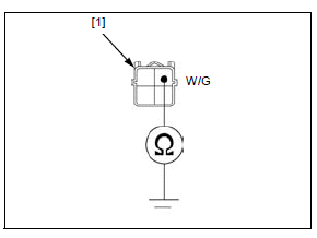
3. O2 Sensor Output Line Short Circuit Inspection
Check the continuity between the wire harness side O2 sensor 4P (Black) connector [1] terminal and ground.
CONNECTION: White/green - Ground
Is there continuity?
YES - Short circuit in White/green wire
NO - GO TO STEP 4.
4. O2 Sensor Inspection
Replace the O2 sensor with a known good one.
Connect the ECM 33P connectors.
Erase the DTC.
Start the engine and warm it up until the coolant temperature is 80ºC (176ºF).
Stop the engine.
Check the O2 sensor with the MCS.
Is the DTC 21-1 indicated?
YES - Replace the ECM with a known good one, and recheck.
NO - Faulty original O2 sensor
DTC 23 (O2 SENSOR HEATER)
Probable cause
- Open circuit in Black/white wire between the main relay and O2 sensor
- Open or short circuit in White or Black/blue wire between the O2 sensor and ECM
- Faulty O2 sensor
- Faulty ECM
DTC 23-1 (O2 SENSOR HEATER)
- Before starting the inspection, check for loose or poor contact on the O2 sensor 4P (Black) and ECM 33P (Gray) connectors, and recheck the DTC.
1. Recheck DTC
Erase the DTC.
Start the engine and check the O2 sensor heater with the MCS.
Is DTC 23-1 indicated?
YES - GO TO STEP 2.
NO - Intermittent failure
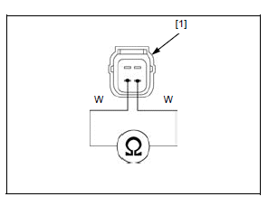
2. O2 Sensor Heater Resistance Inspection
Turn the ignition switch OFF.
Disconnect the O2 sensor 4P (Black) connector.
Measure the resistance between the sensor side O2 sensor 4P (Black) connector [1] terminals.
CONNECTION: White - White
STANDARD: 10 - 40 Ω (20ºC/68ºF)
Is the resistance within standard value?
YES - GO TO STEP 3.
NO - Faulty O2 sensor
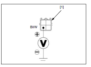
3. O2 Sensor Heater Input Voltage Inspection
Turn the ignition switch ON with the engine stop switch "".
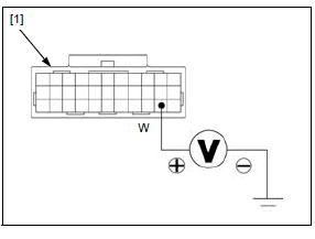
Measure the voltage between the wire harness side O2 sensor 4P (Black) connector [1] and ground.
CONNECTION: Black/white (+) - Ground (-)
Is there battery voltage?
YES - GO TO STEP 4.
NO - Open circuit in Black/white wire
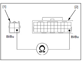
4. O2 Sensor Heater Line Open Circuit Inspection
Disconnect the ECM 33P (Gray) connector.
Check the continuity between the wire harness side O2 sensor 4P (Black) connector [1] and ECM 33P (Gray) connector [2] terminals.
TOOL:
Test probe 07ZAJ-RDJA110
CONNECTION: Black/blue - Black/blue
Is there continuity?
YES - GO TO STEP 5.
NO - Open circuit in Black/blue wire
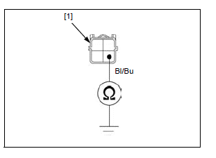
5. O2 Sensor Heater Line Short Circuit Inspection
Check the continuity between the wire harness side O2 sensor 4P (Black) connector [1] terminal and ground.
CONNECTION: Black/blue - ground
Is there continuity?
YES - Short circuit in Black/blue wire
NO - Replace the ECM with a known good one, and recheck.
DTC 29 (IACV)
Probable cause
- Open or short circuit in Yellow/green, Violet/white, Gray/red or Pink/black wire between the IACV and ECM
- Faulty IACV
- Faulty ECM
DTC 29-1 (IACV)
- Before starting the inspection, check for loose or poor contact on the IACV 4P (Black) and ECM 33P (Black) connectors, and recheck the DTC.
1. Recheck DTC
Erase the DTC.
Check the IACV with the MCS.
Is the DTC 29-1 indicated?
YES - GO TO STEP 2.
NO - Intermittent failure
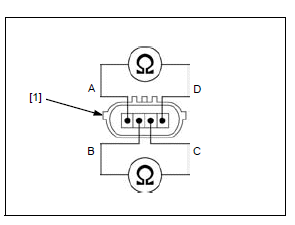
2. IACV Resistance Inspection
Turn the ignition switch OFF.
Lift the fuel tank and support it.
Disconnect the IACV 4P (Black) connector.
Measure the resistance between the 4P connector terminals of the IACV [1].
TOOL:
Test probe 07ZAJ-RDJA110
CONNECTION:
A - D
B - C
STANDARD: 110 - 150 Ω (25ºC/77ºF)
Is the resistance within standard value?
YES - GO TO STEP 3.
NO - Faulty IACV
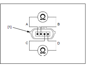
3. IACV Internal Short Circuit Inspection
Check for continuity between the 4P connector terminals of the IACV [1].
TOOL: Test probe 07ZAJ-RDJA110
CONNECTION:
A - B
C - D
Is there continuity?
YES - Faulty IACV.
NO - GO TO STEP 4.
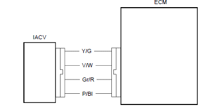
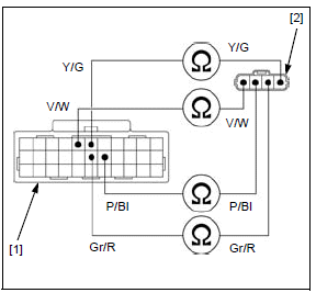
4. IACV Line Open Circuit Inspection
Disconnect the ECM 33P (Black) connector.
Check for continuity between the wire harness side ECM 33P (Black) connector [1] and IACV 4P (Black) connector [2] terminals.
TOOL:
Test probe (2 required) 07ZAJ-RDJA110
CONNECTION:
Yellow/green - Yellow/green
Violet/white - Violet/white
Gray/red - Gray/red
Pink/black - Pink/black
Is there continuity?
YES - GO TO STEP 5.
NO -
- Open circuit in Yellow/green or Violet/ white wire
- Open circuit in Gray/red or Pink/black wire
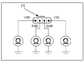
5. IACV Line Short Circuit Inspection Check for continuity between the wire harness side IACV 4P (Black) connector [1] terminals and ground.
TOOL:
Test probe 07ZAJ-RDJA110
CONNECTION:
Yellow/green - Ground
Violet/white - Ground
Gray/red - Ground
Pink/black - Ground
Is there continuity?
YES -
- Short circuit in Yellow/green or Violet/ white wire
- Short circuit in Gray/red or Pink/black wire
NO - Replace the ECM with a known good one, and recheck.
DTC 54 (BANK ANGLE SENSOR)
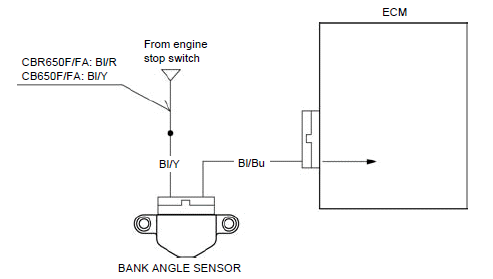
Probable cause
- CBR650F/FA: Open circuit in Black/red or Black/ yellow wire between the engine stop switch and bank angle sensor
- CB650F/FA: Open circuit in Black/yellow wire between the engine stop switch and bank angle sensor
- Open or short circuit in Black/blue wire between the bank angle sensor and ECM
- Faulty bank angle sensor
- Faulty ECM
DTC 54-1 (BANK ANGLE SENSOR LOW VOLTAGE)
- Before starting the inspection, check for loose or poor contact on the bank angle sensor 2P (Black) and E
1. Bank Angle Sensor System Inspection
Erase the DTC.
Check the bank angle sensor with the MCS.
Is about 0 V indicated?
YES - GO TO STEP 2.
NO - Intermittent failure
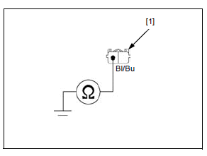
2. Bank Angle Sensor Signal Line Short Circuit Inspection
Turn the ignition switch OFF.
Disconnect the bank angle sensor 2P (Black) connector.
Check for continuity between the wire harness side bank angle sensor 2P (Black) connector [1] terminal and ground.
CONNECTION: Black/blue - Ground
Is there continuity?
YES - Short circuit in the Black/blue wire.
NO - GO TO STEP 3.
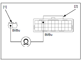
3. Bank Angle Sensor Signal Line Open Circuit Inspection
Disconnect the ECM 33P (Gray) connector.
Check for continuity between the wire harness side bank angle sensor 2P (Black) connector [1] and ECM 33P (Gray) connector [2] terminals.
TOOL:
Test probe 07ZAJ-RDJA110
CONNECTION: Black/blue - Black/blue
Is there continuity?
YES - GO TO STEP 4.
NO - Open circuit in the Black/blue wire
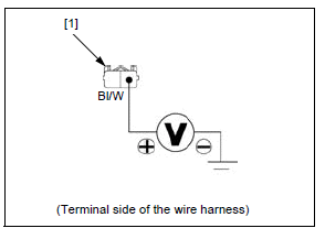
4. Bank Angle Sensor Input Voltage Inspection
Temporarily install the ECM to the wire harness by connecting the 33P (Black) connector.
Turn the ignition switch ON with the engine stop switch "".
Measure the voltage between the wire harness side bank angle sensor 2P (Black) connector [1] terminal and ground.
CONNECTION: Black/white (+) - Ground (-)
Is there battery voltage?
YES - GO TO STEP 5.
NO - Open circuit in Black/white wire
5. Bank Angle Sensor Inspection
Check the bank angle sensor.
Is the bank angle sensor normal?
YES - Replace the ECM with a known good one, and recheck.
NO - Faulty bank angle sensor
DTC 54-2 (BANK ANGLE SENSOR HIGH VOLTAGE)
1. Bank Angle Sensor System Inspection
Erase the DTC.
Check the bank angle sensor with the MCS.
Is about 5 V indicated?
YES - GO TO STEP 2.
NO - Intermittent failure
2. Bank Angle Sensor Inspection
Replace the bank angle sensor with a known good one.
Erase the DTC.
Check the bank angle sensor with the MCS.
Is DTC 54-2 indicated?
YES - Replace the ECM with a known good one, and recheck.
NO - Faulty original bank angle sensor
DTC 86 (SERIAL COMMUNICATION MALFUNCTION)
NOTE:
- Before starting the inspection, check the following connectors for loose
or poor contact and the fuse for blown.
- Front sub harness 12P (Black) and 6P (Black)
- ECM 33P (Black) and 33P (Gray)
- Combination meter 16P (Gray)
- METER TAIL LICENSE PO fuse (7.5 A)
- ODO/TURN fuse (7.5 A)
DTC 86-1 (SERIAL COMMUNICATION)
1. Recheck DTC
Erase the DTC.
Check the serial communication with the MCS.
Is DTC 86-1 indicated?
YES - GO TO STEP 2.
NO - Intermittent failure
2. ECM Serial Communication Output Voltage Inspection
Turn the ignition switch OFF.
Remove the following:
- Left upper cowl A (CBR650F/FA)
- Left tank shroud A (CB650F/FA)
Disconnect the front sub wire harness 12P (Black) connector [1].
Short the DLC terminals using the SCS connector.
Open the throttle grip fully, hold it and turn the ignition switch ON with the
engine stop switch "".
Wait for more than 10 seconds and release the throttle grip.
NOTE:
- The ECM enters the communication diagnostic output mode. The open circuit in the ECM can be checked in this mode.
Measure the voltage between the main wire harness side 12P (Black) connector [1] terminal and ground.
CONNECTION: White (+) - ground (-)
Does the voltage repeat 0 V to 8 V or more at intervals of 5 seconds?
YES - GO TO STEP 3.
NO - Replace the ECM with a known good one, and recheck.
3. Combination Meter Serial Communication Output Voltage Inspection
Turn the ignition switch OFF.
Remove the SCS connector.
Connect the front sub harness 12P (Black) connector.
Disconnect the ECM 33P (Gray) connector.
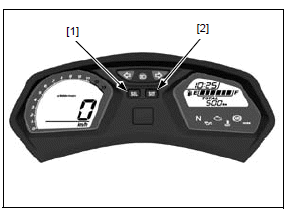
Push and hold combination meter buttons SEL [1] and SET [2], turn the ignition
switch ON with the engine stop switch "".
Wait for more than 10 seconds and release the buttons.
NOTE:
- The combination meter enters the communication diagnostic output mode. The open circuit in the combination meter can be checked in this mode.
Measure the voltage between the wire harness side ECM 33P (Gray) connector [1] terminal and ground.
TOOL:
Test probe 07ZAJ-RDJA110
CONNECTION: White (+) - Ground (-)
Does the voltage repeat 0 V to 8 V or more at intervals of 5 seconds?
YES - GO TO STEP 4.
NO - Replace the combination meter with a known good one, and recheck.
4. Combination Meter Back-up Voltage Inspection
Turn the ignition switch OFF.
Disconnect the combination meter 16P (Gray) connector.
Connect the front sub harness 12P (Black) connector (CB650F/FA only).
Measure the voltage between the combination meter 16P (Gray) connector [1] terminal and ground.
CONNECTION: Red/white (+) - Ground (-)
Is there battery voltage?
YES - Intermittent failure
NO - Open circuit in Red/white wire between the fuse box 2 and combination meter
See also:
 Honda CBR650 - Service manual > PGM-FI troubleshooting information/symptom troubleshooting
PGM-FI troubleshooting information GENERAL TROUBLESHOOTING Intermittent Failure The term "intermittent failure" means a system may have had a failure, but it checks OK now. If the MIL does not come on, check for poor contact or loose pins at all connectors related to the circuit that of the troubleshooting. If the MIL was on, but then went out, the original problem may be intermittent.
Honda CBR650 - Service manual > MIL circuit troubleshooting/ECM
MIL circuit troubleshooting Check that the MIL [1] comes on for 2 seconds and goes off when the ignition switch is turned ON with the engine stop switch "".
 Rider's Manual BMW R 1250 GS GSA
 Owner's Manual Harley-Davidson Sportster XL1200X Forty-Eight
 Owner's Manual Honda CBR650R
 Service manual Honda CBR650
 Owner's Manual Honda PCX125
 Owner's Manual Kawasaki Z1000SX
 Service manual Kawasaki Z1000SX
 Owner's Manual Lexmoto Echo
 Owner's Manual Royal Enfield Interceptor 650
 Service manual Royal Enfield Interceptor 650
 Owner's Manual Yamaha MT-07