 Honda CBR650 - Service manual > MIL circuit troubleshooting/ECM
MIL circuit troubleshooting
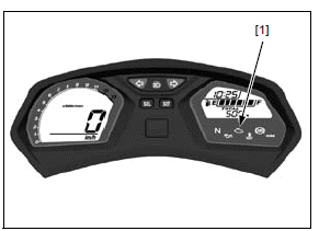
Check that the MIL [1] comes on for 2 seconds and goes off when the ignition
switch is turned ON with the engine stop switch " ".
".
NOTE:
- If the MIL and digital display do not function at all, refer to combination meter initial operation check.
If the engine stop switch is in " ",
the MIL will stay on even when the system is normal.
",
the MIL will stay on even when the system is normal.
If the MIL stays on and the other indications function normally, check the combination meter indication when the serial communication line is abnormal.
If the indication is not according to above condition, check as follows.
Turn the ignition switch OFF.
Disconnect the ECM 33P (Gray) connector.
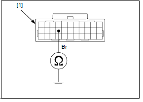
Check for continuity between the wire harness side ECM 33P (Gray) connector [1] terminal and ground.
TOOL:
Test probe 07ZAJ-RDJA110
CONNECTION: Brown - Ground
If there is continuity, check for short circuit in the Brown wire between the DLC and ECM.
If there is no continuity, replace the ECM with a known good one, and recheck.
ECM
REMOVAL/ INSTALLATION
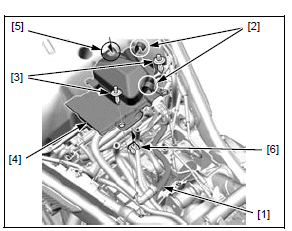
Lift the fuel tank and support it.
Release the radiator siphon hose [1] from the wire guides [2].
Remove the two clips [3].
Remove the ABS modulator cover [4] by releasing the slot [5] from the tab [6] of the ABS modulator tray.
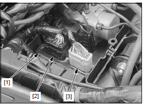
Turn the ignition switch OFF.
Pull out the ECM [1] from the ABS modulator tray, then disconnect the ECM 33P (Black) [2] and 33P (Gray) [3] connectors.
Installation is in the reverse order of removal.
NOTE:
- If the ECM is replaced, perform the Key Registration Procedures.
POWER/GROUND LINE INSPECTION
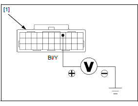
POWER INPUT LINE
Disconnect the ECM 33P (Black) connector.
Measure the voltage between the wire harness side ECM 33P (Black) connector [1] terminal and ground.
TOOL:
Test probe 07ZAJ-RDJA110
CONNECTION: Black/yellow (+) - Ground (-)
There should be battery voltage with the ignition switch turned ON and engine
stop switch "".
If there is no voltage, check the following:
- CBR650F/FA: Black/red or Black/yellow wire between the engine stop switch and ECM
- CB650F/FA: Black/yellow wire between the engine stop switch and ECM
- Engine stop switch.
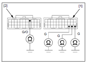
GROUND LINE
Disconnect the ECM 33P (Black) and 33P (Gray) connectors.
Check for continuity between the wire harness side ECM 33P (Black) [1] and 33P (Gray) [2] connector terminals and ground.
TOOL:
Test probe 07ZAJ-RDJA110
CONNECTION:
Green/orange - Ground
Green - Ground
There should be continuity at all times.
If there is no continuity, check for open circuit in the Green/orange or Green wire.
See also:
 Honda CBR650 - Service manual > DTC index
NOTE: If the MCS is not used, perform all of the inspection on the corresponding main code (digits in front of hyphen) of the DTC.
Honda CBR650 - Service manual > Sensors
TP sensor reset procedure Make sure that the DTC is not stored in ECM. If the DTC is stored in ECM, TP sensor reset mode won't start by following the procedure below.
 Rider's Manual BMW R 1250 GS GSA
 Owner's Manual Harley-Davidson Sportster XL1200X Forty-Eight
 Owner's Manual Honda CBR650R
 Service manual Honda CBR650
 Owner's Manual Honda PCX125
 Owner's Manual Kawasaki Z1000SX
 Service manual Kawasaki Z1000SX
 Owner's Manual Lexmoto Echo
 Owner's Manual Royal Enfield Interceptor 650
 Service manual Royal Enfield Interceptor 650
 Owner's Manual Yamaha MT-07