 Honda CBR650 - Service manual > Sensors
TP sensor reset procedure
- Make sure that the DTC is not stored in ECM. If the DTC is stored in ECM, TP sensor reset mode won't start by following the procedure below.
1. Remove the seat.
2. Turn the ignition switch OFF.
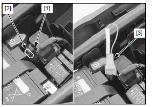
Release the DLC [1] from the stay [2], then remove the dummy connector from the DLC.
3. Connect the special tool to the DLC.
TOOL:
[3] SCS connector 070PZ-ZY30100
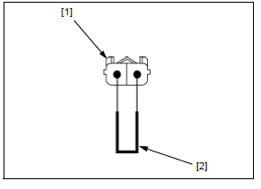
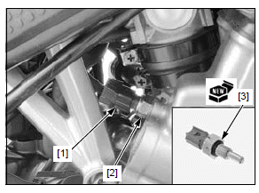
4. Disconnect the ECT sensor 2P (Blue) connector.
Short the wire harness side ECT sensor 2P (Blue) connector [1] terminals with a jumper wire [2].
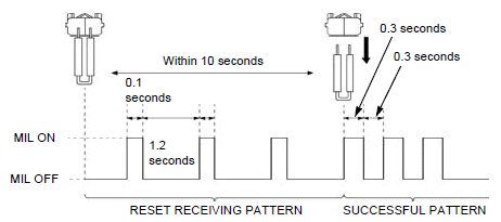
5. Turn the ignition switch ON with the engine stop switch, then disconnect the jumper wire from the ECT sensor 2P (Blue) connector within 10 seconds while the MIL is blinking (reset receiving pattern).
6. Check if the MIL blinks.
After disconnection of the jumper wire, the MIL should start blinking. (successful pattern) If the jumper wire is connected for more than 10 seconds, the MIL will stay on (unsuccessful pattern).
Turn the ignition switch OFF and try again from the step 4.
7. Turn the ignition switch OFF. Remove the special tool and install the DLC into the dummy connector.
8. Install the removed parts in the reverse order of removal.
9. Check the engine idle speed.
MAP sensor
REMOVAL/INSTALLATION
Lift the fuel tank and support it.
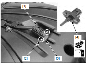
Disconnect the MAP sensor 3P (Black) connector [1].
Remove the screw [2] and MAP sensor [3].
Remove the O-ring [4] from the MAP sensor.
Installation is in the reverse order of removal.
- Replace the O-ring with a new one and coat it with the engine oil.
TORQUE:
MAP sensor mounting screw:
3.4 N*m (0.3 kgf*m, 2.5 lbf*ft)
ECT sensor
REMOVAL/INSTALLATION
Drain the coolant.
Remove the cam chain tensioner lifter.
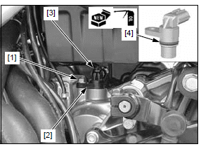
Disconnect the ECT sensor 2P (Blue) connector [1].
Remove the ECT sensor [2] and O-ring [3].
Installation is in the reverse order of removal.
NOTE:
- Replace the O-ring with a new one (do not apply oil).
TORQUE:
ECT sensor: 12 N*m (1.2 kgf*m, 9 lbf*ft)
Fill and bleed the cooling system.
IAT sensor
REMOVAL/INSTALLATION
Lift the fuel tank and support it.
Disconnect the IAT sensor 2P (Black) connector [1].
Remove the screws [2] and IAT sensor [3].
Remove the O-ring [4] from the IAT sensor.
Installation is in the reverse order of removal.
- Replace the O-ring with a new one and coat it with the engine oil.
TORQUE:
IAT sensor screw: 1.1 N*m (0.1 kgf*m, 0.8 lbf*ft)
VS sensor
REMOVAL/INSTALLATION
Remove the bolt [1] and VS sensor [2].
Disconnect the VS sensor 3P (Black) connector [3] and remove the O-ring [4] from the VS sensor.
Installation is in the reverse order of removal.
NOTE:
- Replace the O-ring with a new one and coat it with engine oil.
- Install the O-ring into the groove in the VS sensor.
TORQUE:
VS sensor bolt: 12 N*m (1.2 kgf*m, 9 lbf*ft)
O2 sensor
REMOVAL/INSTALLATION
NOTICE
- Do not get grease, oil or other materials in the O2 sensor air hole.
- The O2 sensor may be damaged if dropped. Replace it with a new one, if dropped.
NOTE:
- Do not service the O2 sensor while it is hot.
- Do not use an impact wrench while removing or installing the O2 sensor, or it may be damaged.
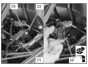
Remove the exhaust pipe/muffler.
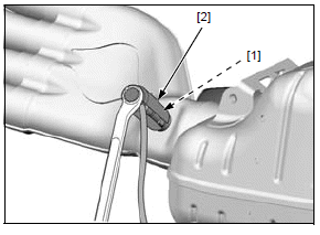
Remove the O2 sensor [1] using the special tool.
TOOL:
[2] Sensor socket wrench 07LAA-PT50101
Install and tighten the O2 sensor to the specified torque.
TORQUE: 24.5 N*m (2.5 kgf*m, 18 lbf*ft)
Bank angle sensor
REMOVAL/INSTALLATION
Remove the air cleaner housing.
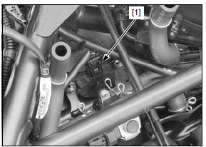
Disconnect the bank angle sensor 2P (Black) connector [1].
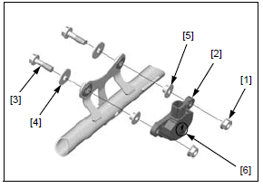
Remove the following:
- Two nuts [1]
- Bank angle sensor [2]
- Two bolts [3] and washers [4]
- Two collars [5]
Installation is in the reverse order of removal.
NOTE:
- Install the bank angle sensor with the "UP" mark [6] facing up.
TORQUE:
Bank angle sensor nut:
8.5 N*m (0.9 kgf*m, 6.3 lbf*ft)
INSPECTION
SYSTEM INSPECTION WITH MCS
Remove the bank angle sensor without disconnecting its connector.
Connect the MCS to the DLC.
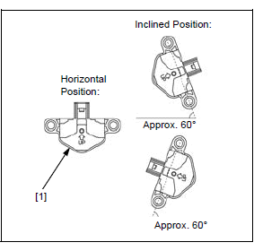
Check the output voltage at each position of the sensor with the MCS.
STANDARD:
Horizontal Position: 7.0 - 8.8 V
Approx. 60º: 0.40 - 0.84 V
FUNCTION CHECK
Remove the bank angle sensor without disconnecting its connector.
Pull out the bank angle sensor from the frame.
Temporarily install the following:
- Air cleaner housing.
- Fuel tank.
Place the bank angle sensor [1] horizontal.
Start the engine.
NOTE:
- Do not crank the engine, when the air cleaner housing is not installed.
Incline the bank angle sensor approximately 60º to the left or right.
The bank angle sensor is normal if the engine stops after a few seconds.
Main relay
CIRCUIT INSPECTION
For relay inspection.
Remove the main relay.
RELAY COIL POWER INPUT LINE
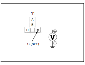
Measure the voltage between the main relay 4P connector [1] terminal and ground.
CONNECTION: C (+) - Ground (-)
There should be battery voltage when the ignition switch is turned ON with
the engine stop switch " ".
".
If there is no voltage, check the following:
- CBR650F/FA: Black/yellow or Black/red wire between the main relay connector and engine stop switch for open circuit
- CB650F/FA: Black/yellow wire between the relay connector and engine stop switch for open circuit
- Engine stop switch.
- White/yellow wire between the engine stop switch and fuse box 1 for open circuit
- ENG STOP (7.5 A) fuse
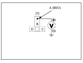
RELAY SWITCH POWER INPUT LINE
Measure the voltage between the main relay terminal of the relay box [1] and ground.
CONNECTION: A (+) - Ground (-)
There should be battery voltage at all times.
If there is no voltage, check the following:
- Black/orange wire between the main relay and fuse box 1 for open circuit
- FI (20 A) fuse
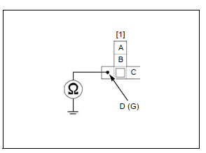
GROUND LINE
Check for continuity between the main relay terminal of the relay box [1] and ground.
CONNECTION: D - Ground
There should be continuity at all times.
If there is no continuity, check for open circuit in the Green wire.
See also:
 Honda CBR650 - Service manual > MIL circuit troubleshooting/ECM
MIL circuit troubleshooting Check that the MIL [1] comes on for 2 seconds and goes off when the ignition switch is turned ON with the engine stop switch "".
Honda CBR650 - Service manual > Ignition system
Service information GENERAL NOTICE The ECM may be damaged if dropped. Also if the connector is disconnected when current is flowing, the excessive voltage may damage the module. Always turn off the ignition switch before servicing. Use spark plug of the correct heat range. Using a spark plug with an incorrect heat range can damage the engine.
 Rider's Manual BMW R 1250 GS GSA
 Owner's Manual Harley-Davidson Sportster XL1200X Forty-Eight
 Owner's Manual Honda CBR650R
 Service manual Honda CBR650
 Owner's Manual Honda PCX125
 Owner's Manual Kawasaki Z1000SX
 Service manual Kawasaki Z1000SX
 Owner's Manual Lexmoto Echo
 Owner's Manual Royal Enfield Interceptor 650
 Service manual Royal Enfield Interceptor 650
 Owner's Manual Yamaha MT-07