 Honda CBR650 - Service manual > Ignition system
Service information
GENERAL
NOTICE
- The ECM may be damaged if dropped. Also if the connector is disconnected when current is flowing, the excessive voltage may damage the module. Always turn off the ignition switch before servicing.
- Use spark plug of the correct heat range. Using a spark plug with an incorrect heat range can damage the engine.
- Some electrical components may be damaged if terminals or connectors are connected or disconnected while the ignition switch is turned ON and current is present.
- A faulty ignition system is often related to poorly connected or corroded terminals. Check those connections before proceeding.
- Make sure the battery is adequately charged. Using the starter motor with a weak battery results in a slower engine cranking speed as well as no spark at the spark plug.
- The ignition timing cannot be adjusted since the ECM is factory preset.
- When servicing the ignition system, always follow the steps in the troubleshooting table.
- For following components information, refer to each section.
- Ignition switch
- Engine stop switch
- Main relay
- Bank angle sensor
- Sidestand switch
- Neutral switch
- Neutral diode
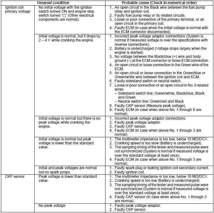
Troubleshooting
- Inspect the following before diagnosing the system.
- Faulty spark plug
- Loose spark plug cap or spark plug wire connection
- Water got into the spark plug cap (Leaking the ignition coil secondary current)
- If there is no spark at cylinder, temporarily exchange the ignition coil with a known good one and perform the spark test. If there is spark, the original ignition coil is faulty.
- "Initial voltage" of the ignition primary coil is the battery voltage
with the ignition switch turned ON and engine stop switch turned "
 "
(The engine is not cranked by the starter motor).
"
(The engine is not cranked by the starter motor).
No spark at spark plug
System location
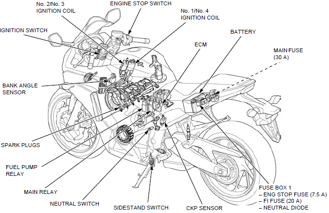
- IGNITION SWITCH
- ENGINE STOP SWITCH
- No. 2/No. 3 IGNITION COIL
- No. 1/No. 4 IGNITION COIL
- ECM
- BATTERY
- MAIN FUSE (30 A)
- FUSE BOX 1
- ENG STOP FUSE (7.5 A)
- FI FUSE (20 A)
- NEUTRAL DIODE
- CKP SENSOR
- SIDESTAND SWITCH
- NEUTRAL SWITCH
- MAIN RELAY
- FUEL PUMP RELAY
- SPARK PLUGS
- BANK ANGLE SENSOR
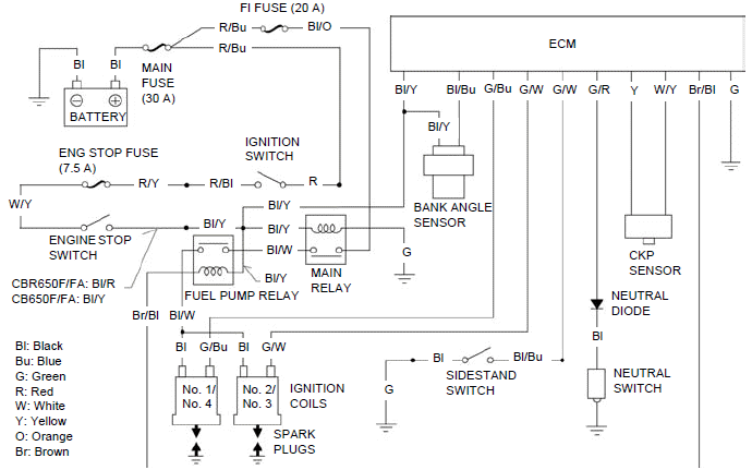
System diagram
Ignition system inspection
NOTE:
- If there is no spark at the plug, check all connections for loose or poor contact before measuring the peak voltage.
- Use a commercially available digital multimeter with an impedance of 10 MΩ/DCV minimum.
- The display value differs depending upon the internal impedance of the multimeter.
- If using the Imrie diagnostic tester (model 625), follow the manufacturer's instructions.
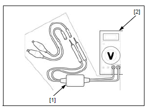
Connect the peak voltage adaptor [1] to the digital multimeter [2], or use the Imrie diagnostic tester.
TOOL:
Imrie diagnostic tester (model 625) or Peak voltage adaptor 07HGJ-0020100 with
commercially available digital multimeter (impedance 10 MΩ/DCV minimum)
IGNITION COIL PRIMARY PEAK VOLTAGE
NOTE:
- Check all system connections before performing this inspection. Loose connectors can cause incorrect readings.
- Check the cylinder compression and check that the spark plugs are installed correctly in the cylinder head.
Disconnect the spark plug caps from the spark plugs.
Connect a known good spark plug [1] to the spark plug cap and ground it to the cylinder head as done in a spark test.
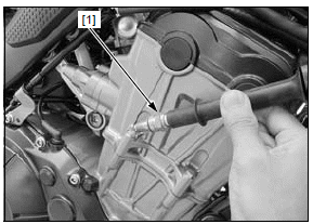
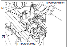
With the connectors connected, connect the peak voltage adaptor or Imrie tester probes to the ignition coil primary terminal [1] and ground.
CONNECTION:
No. 1/No. 4 ignition coil [2]:
Green/Blue (+) - Ground (-)
No. 2/No. 3 ignition coil [3]:
Green/white (+) - Ground (-)
Turn the ignition switch ON with the engine stop switch ""
and check the initial voltage at this time.
The battery voltage should be measured.
If the initial voltage cannot be measured, follow the checks described in the troubleshooting table.
Shift the transmission into neutral.
Crank the engine with the starter motor and read ignition coil primary peak voltage.
Avoid touching the spark plug and tester probes to prevent electric shock.
NOTE:
- Although measured values are different for each ignition coil, they are normal as long as voltage is higher than the specified value.
If the peak voltage is lower than the standard value, follow the checks described in the troubleshooting table.
Install the removed parts in the reverse order of removal.
CKP SENSOR PEAK VOLTAGE
NOTE:
- Check the cylinder compression and check that the spark plugs are installed correctly in the cylinder head.
Disconnect the ECM 33P (Black) and 33P (Gray) connectors.
Connect the peak voltage adaptor [1] or Imrie tester probes to the ECM 33P (Black) [2] and 33P (Gray) [3] connector terminals of the wire harness side, using the test probes.
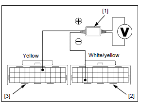
TOOL:
Test probe (2 required) 07ZAJ-RDJA110
CONNECTION: Yellow (+) - White/yellow (-)
Shift the transmission into neutral and turn the ignition switch ON with the
engine stop switch "".
Crank the engine with the starter motor and measure the CKP sensor peak voltage.
PEAK VOLTAGE: 0.7 V minimum
If the peak voltage measured at the ECM 33P connectors is abnormal, measure the peak voltage at the CKP sensor connector.
Turn the ignition switch OFF.
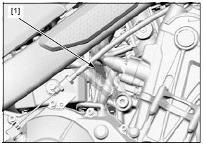
Disconnect the CKP sensor 2P (Black) connector [1].
Connect the peak voltage adaptor or Imrie tester probes to the 2P (Black) connector terminals of the CKP sensor side.
CONNECTION: Yellow (+) - White/yellow (-)
In the same manner as at the ECM 33P connectors, measure the peak voltage and compare it to the voltage measured at the ECM 33P connectors.
NOTE:
- If the peak voltage measured at the ECM is abnormal and the one measured at the CKP sensor is normal, the wire harness has an open or short circuit or loose connection.
- If the peak voltage of the CKP sensor side is lower than standard value, follow the checks described in the troubleshooting table.
For CKP sensor replacement.
Install the removed parts in the reverse order of removal.
Ignition timing
NOTE:
- The ignition timing cannot be adjusted since the ECM is factory preset.
Remove the following:
- Left middle cowl (CBR650F/FA)
- Left tank shroud B (CB650F/FA)
Start the engine, warm it up to normal operating temperature and stop it.
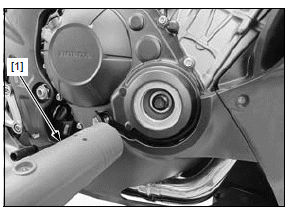
Stop the engine and remove the timing hole cap.
Read the instructions for timing light operation.
Connect the timing light [1] to the No.1 spark plug wire.
Start the engine and let it idle.
IDLE SPEED: 1,250 +- 100 min-1 (rpm)
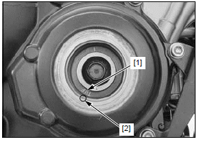
The ignition timing is correct if the "F" mark [1] on the primary drive gear aligns with the index notch [2] in the right crankcase cover.
Coat a new O-ring with engine oil and install it into the groove in the timing hole cap.
Apply grease to the threads of the timing hole cap and install it.
Tighten the timing hole cap to the specified torque.
TORQUE:18 N*m (1.8 kgf*m, 13 lbf*ft)
Remove the timing light.
Install the removed parts in the reverse order of removal.
Ignition coil
REMOVAL/INSTALLATION
Disconnect the spark plug caps.
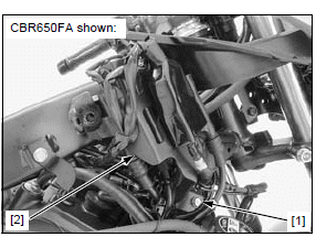
Remove the bolt [1] and release the ignition coil stay assembly [2] from the frame.
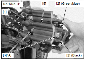
Release the wire clamp [1].
Disconnect the ignition coil wire connectors [2] Remove the bolts [3], spacers [4] and No.1/No.4 ignition coil [5].
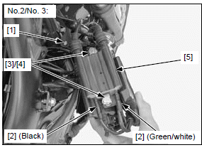
Release the wire clip [1].
Disconnect the ignition coil wire connectors [2] Remove the bolts [3], spacers [4] and No.2/No.3 ignition coil [5].
Installation is in the reverse order of removal.
NOTE:
- Do not interchange the ignition coils.
CKP sensor
REMOVAL/INSTALLATION
Remove the right crankcase cover.
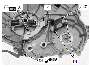
Remove the CKP sensor wire clamp bolts [1] and wire clamp [2].
Remove the wire grommet [3] from the right crankcase cover.
Remove the CKP sensor mounting bolts [4] and CKP sensor [5].
Installation is in the reverse order of removal.
- Apply locking agent to the CKP sensor wire clamp bolt threads.
- Apply sealant (TB1207B manufactured by ThreeBond or an equivalent) to the wire grommet seating surface.
See also:
 Honda CBR650 - Service manual > Sensors
TP sensor reset procedure Make sure that the DTC is not stored in ECM. If the DTC is stored in ECM, TP sensor reset mode won't start by following the procedure below.
Honda CBR650 - Service manual > Electric starter
Service information GENERAL NOTICE If the current is kept flowing through the starter motor turn it while the engine is not cranking over, the starter motor may be damaged. The starter motor can be serviced with the engine installed in the frame. Always turn the ignition switch OFF before servicing the starter motor. The motor could suddenly start, causing serious injury. A weak battery may be unable to turn the starter motor quickly enough, or supply adequate ignition current. When servicing the starter system, always follow the steps in the troubleshooting flow chart. For following components information, refer to Lights/Meters/Switches section. Ignition switch Engine stop switch Starter switch Clutch switch Sidestand switch Neutral switch
 Rider's Manual BMW R 1250 GS GSA
 Owner's Manual Harley-Davidson Sportster XL1200X Forty-Eight
 Owner's Manual Honda CBR650R
 Service manual Honda CBR650
 Owner's Manual Honda PCX125
 Owner's Manual Kawasaki Z1000SX
 Service manual Kawasaki Z1000SX
 Owner's Manual Lexmoto Echo
 Owner's Manual Royal Enfield Interceptor 650
 Service manual Royal Enfield Interceptor 650
 Owner's Manual Yamaha MT-07