 Honda CBR650 - Service manual > Electric starter
Service information
GENERAL
NOTICE
If the current is kept flowing through the starter motor turn it while the engine is not cranking over, the starter motor may be damaged.
- The starter motor can be serviced with the engine installed in the frame.
- Always turn the ignition switch OFF before servicing the starter motor. The motor could suddenly start, causing serious injury.
- A weak battery may be unable to turn the starter motor quickly enough, or supply adequate ignition current.
- When servicing the starter system, always follow the steps in the troubleshooting flow chart.
- For following components information, refer to Lights/Meters/Switches
section.
- Ignition switch
- Engine stop switch
- Starter switch
- Clutch switch
- Sidestand switch
- Neutral switch
Troubleshooting
NOTE:
- Make sure the battery is fully charged and in good condition.
- Check for a blown main fuse (30 A) and sub fuse (ENG STOP; 7.5 A). (Check for a short circuit in the related wires if the fuse is blown again)
- The starter motor should operate with the following conditions:
- Transmission in neutral or clutch lever squeezed with sidestand retracted
- Ignition switch turned ON with engine stop switch turned "
 "
" - Starter switch pushed
Starter motor does not turn
1. Starter Relay Switch Operation Inspection
Check the operation of the starter relay switch as above starting conditions.
Does the starter relay switch click?
YES - GO TO STEP 2.
NO - GO TO STEP 3.
2. Starter Motor Inspection
Apply battery voltage directly to the starter motor and check the operation. (A large amount of current flows, so do not use a thin wire)
Does the starter motor turn?
YES -
- Poorly contacted starter motor cable
- Faulty starter relay switch
NO - Faulty starter motor
3. Relay Coil Power Input Line Inspection
Check the power input line of the starter relay switch.
Is the input line normal?
YES - GO TO STEP 4.
NO -
- Faulty ignition switch
- Faulty engine stop switch
- Faulty starter switch
- Loose or poor contact of the related connector terminal
- Open circuit in wire harness
4. Relay Coil Ground Line Inspection
Check the ground line of the starter relay switch.
Is the ground line normal?
YES - GO TO STEP 5.
NO -
- Faulty neutral switch
- Faulty neutral diode
- Faulty sidestand switch
- Faulty clutch switch
- Loose or poor contact of the related connector terminal
- Open circuit in wire harness
5. Starter Relay Switch Inspection
Check the starter relay switch.
Is the starter relay switch normal?
YES - Loose or poor contact of the starter relay switch connector terminal
NO - Faulty starter relay switch
Starter motor turns slowly
- Low battery voltage
- Poorly connected battery cables
- Poorly connected starter motor cable
- Faulty starter motor
Starter motor turns, but engine does not turn
- Faulty starter clutch or starter gear train
- Faulty ignition system
System location
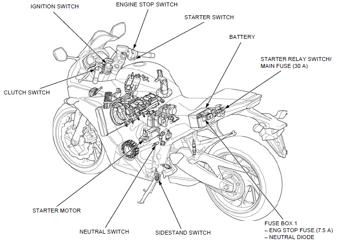
- CLUTCH SWITCH
- IGNITION SWITCH
- ENGINE STOP SWITCH
- STARTER SWITCH
- BATTERY
- STARTER RELAY SWITCH/ MAIN FUSE (30 A)
- FUSE BOX 1
- ENG STOP FUSE (7.5 A)
- NEUTRAL DIODE
- SIDESTAND SWITCH
- NEUTRAL SWITCH
- STARTER MOTOR
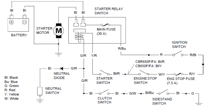
System diagram
Starter motor
REMOVAL/INSTALLATION
Disconnect the negative (-) cable from the battery.
Release the terminal cap [1].
Remove the terminal nut [2] and disconnect the starter motor cable [3].
Remove the two mounting bolts [4] and negative (-) cable [5].
Remove the starter motor [6] from the crankcase.
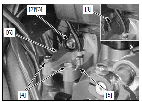
Remove the O-ring [1].
Installation is in the reverse order of removal.
NOTE:
- Replace the O-ring with a new one and coat it with engine oil.
DISASSEMBLY/ASSEMBLY
Disassemble and assemble the starter motor as following illustration.
NOTICE
The coil may be damaged if the magnet pulls the armature against the motor case.
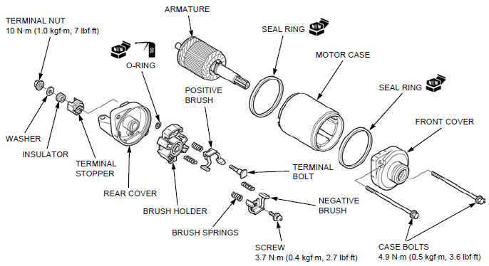
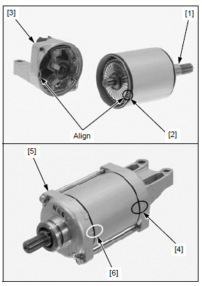
NOTE:
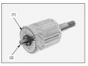
- Install the armature [1] into the motor case from the case groove [2] side so the commutator bars facing to the rear side.
- When installing the rear cover [3], align the tab with the groove (the index lines [4] are aligned).
- When installing the front cover [5], take care to prevent damaging the oil seal lip with the armature shaft. Align the index lines [6] on the front cover and motor case.
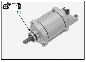
INSPECTION
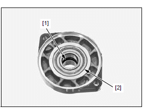
FRONT COVER
Check the oil seal [1] in the front cover for deterioration, wear or damage.
Turn the inner race of bearing [2] with your finger.
The bearings should turn smoothly and quietly.
Also check that the outer race fits tightly in the front cover.
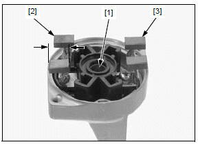
REAR COVER
Check the bushing [1] in the rear cover for wear or damage.
Inspect the brushes for damage and measure the brush length.
SERVICE LIMIT: 6.5 mm (0.26 in)
Check for continuity on the rear cover as follows:
- Between the positive brush [2] and cable terminal; there should be continuity.
- Between the cable terminal and rear cover; there should be no continuity.
- Between negative brush [3] and rear cover; there should be continuity.
ARMATURE
Do not use emery or sand paper on the commutator.
Clean the metallic debris off the commutator bars [1].
Check the commutator bars for discoloration.
Check for continuity on the armature as follows:
- Between pair of commutator bars; there should be continuity.
- Between each commutator bar and the armature shaft [2]; there should be no continuity.
Starter relay switch
OPERATION INSPECTION
Remove the seat.
Shift the transmission into neutral or squeeze the clutch lever with the sidestand retracted.
Turn the ignition switch ON with the engine stop switch turned " ".
Push the starter switch.
".
Push the starter switch.
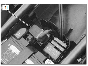
The coil is normal if the starter relay switch [1] clicks.
If you don't hear the starter relay switch "CLICK", inspect the relay coil circuits.
RELAY COIL CIRCUIT INSPECTION
POWER INPUT LINE
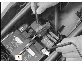
Release the connector boot from the starter relay switch 4P (Red) connector [1].
Turn the ignition switch ON with the engine stop switch turned "".
Measure the voltage between the 4P (Red) connector terminal and ground.
CONNECTION: Yellow/red (+) - Ground (-)
There should be battery voltage when the starter switch is pushed.
GROUND LINE
Turn the ignition switch OFF.
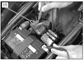
Disconnect the starter relay switch 4P (Red) connector [1].
Check for continuity between the 4P (Red) connector terminal and ground.
CONNECTION: Green/red - Ground
There should be continuity when the transmission is in neutral or when the clutch lever is squeezed with the sidestand retracted (In neutral, there is a slight resistance due to the diode).
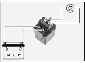
RELAY INSPECTION
Remove the starter relay switch.
Connect a 12 V battery to the starter relay switch as shown.
There should be continuity between the cable terminals when the battery is connected, and no continuity when the battery is disconnected.
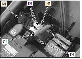
REMOVAL/INSTALLATION
Remove the seat.
Disconnect the negative (-) cable from the battery.
Disconnect the starter relay switch 4P (Red) connector [1].
Release the terminal cover [2], and remove the socket bolts [3] to disconnect the cables.
Remove the starter relay switch [4] from the stays [5].
Installation is in the reverse order of removal.
Neutral diode
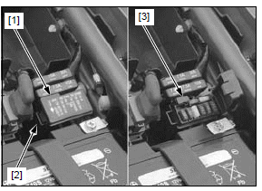
INSPECTION
Remove the seat.
Open the cover [1] on the fuse box 1 by releasing the tab [2].
Remove the neutral diode [3].
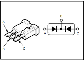
Check for continuity between the diode terminals.
When there is continuity, a small resistance value will register.
If there is continuity in direction shown by the arrow, the diode is normal.
See also:
 Honda CBR650 - Service manual > Ignition system
Service information GENERAL NOTICE The ECM may be damaged if dropped. Also if the connector is disconnected when current is flowing, the excessive voltage may damage the module. Always turn off the ignition switch before servicing. Use spark plug of the correct heat range. Using a spark plug with an incorrect heat range can damage the engine.
 Rider's Manual BMW R 1250 GS GSA
 Owner's Manual Harley-Davidson Sportster XL1200X Forty-Eight
 Owner's Manual Honda CBR650R
 Service manual Honda CBR650
 Owner's Manual Honda PCX125
 Owner's Manual Kawasaki Z1000SX
 Service manual Kawasaki Z1000SX
 Owner's Manual Lexmoto Echo
 Owner's Manual Royal Enfield Interceptor 650
 Service manual Royal Enfield Interceptor 650
 Owner's Manual Yamaha MT-07