 Kawasaki Z1000SX - Service manual > Replacement Parts
Air Cleaner Element Replacement
NOTE
- In dusty areas, the element should be replaced more frequently than the recommended interval.
WARNING If dirt or dust is allowed to pass through into the throttle body assy, the throttle may become stuck, possibly causing accident. Replace the air cleaner element according to the maintenance chart.
NOTICE If dirt gets through into the engine, excessive engine wear and possibly engine damage will occur.
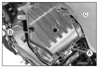
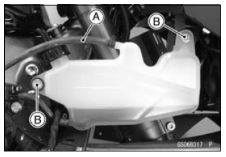
- Remove:
Fuel Tank (see Fuel Tank Removal in the Fuel System (DFI) chapter)
Connector Bracket [A]
Screws [B]
Upper Air Cleaner Housing [C]
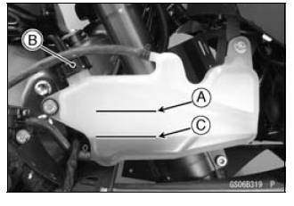
- Discard the air cleaner element [A].
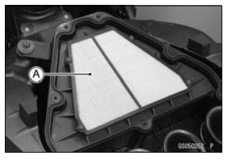
- Install a new element so that flat side faces forward.
- Tighten:
Torque - Upper Air Cleaner Housing Screws: 1.1 N*m (0.11 kgf*m, 9.7 in*lb)
Fuel Hose Replacement
- Remove the fuel tank (see Fuel Tank Removal in the Fuel System (DFI) chapter).
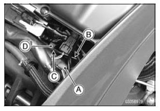
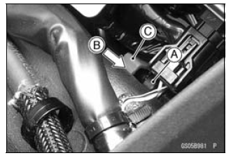
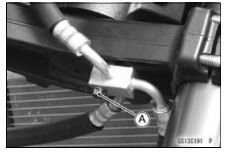
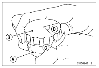
- Be sure to place a piece of cloth [A] around the fuel hose joint.
- Insert a thin blade screwdriver [B] into the slit [C] on the joint lock [D].
- Turn the driver to disconnect the joint lock.
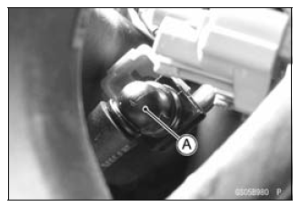
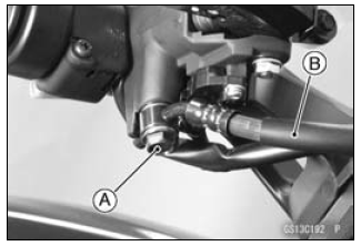
- Pull the fuel hose joint [A] out of the delivery pipe.
WARNING Fuel is flammable and explosive under certain conditions and can cause severe burns. Be prepared for fuel spillage; any spilled fuel must be completely wiped up immediately. When the fuel hose is disconnected, fuel spills out from the hose and the pipe. Cover the hose connection with a clean shop towel to prevent fuel spillage.
- Replace the fuel hose with a new one.
- Run the fuel hose correctly (see Cable, Wire, and Hose Routing section in the Appendix chapter).
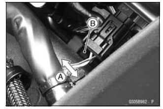
- Insert the fuel hose joint [A] straight onto the delivery pipe until the hose joint clicks.
- Push [B] the joint lock [C].
- Push and pull [A] the fuel hose joint [B] back and forth more than two times and make sure it is locked and does not come off.
WARNING Leaking fuel can cause a fire or explosion resulting in severe burns. Make sure the fuel hose joint is installed correctly on the delivery pipe and that it doesn't leak.
If it comes off, reinstall the hose joint.
- Run the fuel hose correctly (see Cable, Wire, and Hose Routing section in the Appendix chapter).
- Install the fuel tank (see Fuel Tank Installation in the Fuel System (DFI) chapter).
- Start the engine and check the fuel hose for leaks.
Coolant Change
WARNING Coolant can be extremely hot and cause severe burns, is toxic and very slippery. Do not remove the radiator cap or attempt to change the coolant when the engine is hot; allow it cool completely.
Immediately wipe any spilled coolant from tires, frame, engine or other painted parts. Do not ingest coolant.
- Remove the left lower fairing (see Lower Fairing Removal in the Frame chapter).
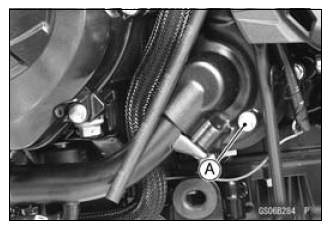
- Place a container under the coolant drain bolt [A], then remove the drain bolt.
- Remove the right center fairing (see Center Fairing Removal in the Frame chapter).
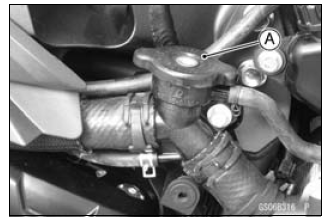
- Remove the radiator cap [A] in two steps. First turn the cap
counterclockwise to the first stop. Then push and turn it further in the
same direction and remove the cap.
- The coolant will drain from the radiator and engine.
- Remove:
Right Lower Fairing Assembly (see Lower Fairing Assembly Removal in the Frame chapter)
Hose [A]
Reserve Tank Bolts [B] - Turn over the reserve tank, remove the cap, and pour the coolant into a suitable container.
- Install the reserve tank.
- Replace the drain bolt gasket with a new one.
- Tighten the drain bolt with the gasket.
Torque - Coolant Drain Bolt: 11 N*m (1.1 kgf*m, 97 in*lb)
- When filling the coolant, choose a suitable mixture ratio by referring to the coolant manufacturer's directions.
NOTICE Soft or distilled water must be used with the antifreeze in the cooling system.
If hard water is used in the system, it causes scales accumulation in the water passages, and considerably reduces the efficiency of the cooling system.
Water and Coolant Mixture Ratio (Recommended)
Soft Water: 50%
Coolant: 50%
Freezing Point: -35ºC (-31ºF)
Total Amount: 2.9 L (3.1 US qt)
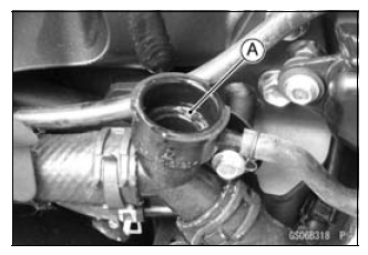
- Fill the radiator up to the filler neck [A] with coolant.
NOTE
- Pour in the coolant slowly so that it can expel the air from the engine and radiator.
- Check the cooling system for leaks.
- Tap the radiator hoses to force any air bubbles caught inside.
- Fill the radiator up to the filler neck with coolant.
- Fill the reserve tank up to the "F" (full) level line [A] with coolant and install the cap [B].
- Start the engine, warm it up thoroughly until the radiator fan turns on and then stop the engine.
- Check the coolant level in the reserve tank after the engine cools down.
If the coolant level is lower than the "L" (low) level line [C], add coolant to the "F" level line.
NOTICE Do not add more coolant above the "F" level line.
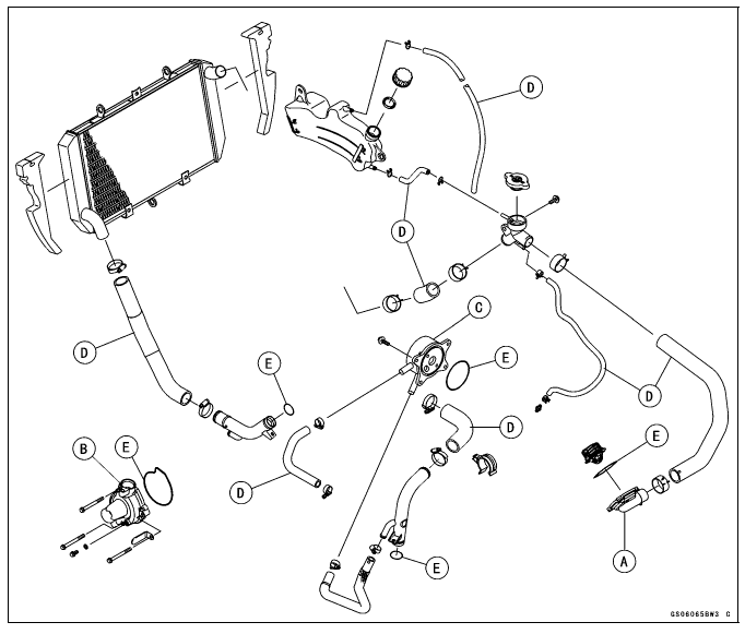
Radiator Hose and O-ring Replacement
- Drain the coolant (see Coolant Change).
- Remove:
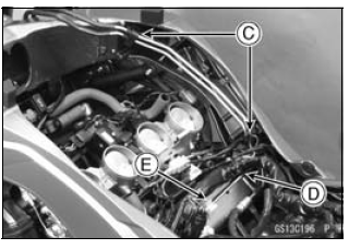
Thermostat Housing [A] (see Thermostat Removal in the Cooling System chapter)
Water Pump Cover [B] (seeWater Pump Removal in the Cooling System chapter)
Oil Cooler [C] (see Oil Cooler Removal in the Engine Lubrication System chapter) - Replace the hoses [D] and O-rings [E] with new ones.
- Apply grease to the O-rings and install them.
- Install the hoses and tighten the clamps securely.
Torque - Radiator (Water) Hose Clamp Screws: 2.9 N*m (0.30 kgf*m, 26 in*lb)
- Fill the coolant (see Coolant Change).
- Check the cooling system for leaks.
Engine Oil Change
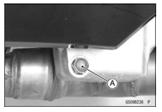
- Situate the motorcycle so that it is vertical after warming up the engine.
- Remove the engine oil drain bolt [A] to drain the oil.
- The oil in the oil filter can be drained by removing the filter (see Oil Filter Replacement).
- Replace the drain bolt gasket with a new one.
- Tighten:
Torque - Engine Oil Drain Bolt: 29 N*m (3.0 kgf*m, 21 ft*lb) - Pour in the specified type and amount of oil.
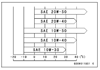
Recommended Engine Oil
Type: API SG, SH, SJ, SL or SM with JASO MA, MA1 or MA2
Viscosity: SAE 10W-40
Capacity:
3.2 L (3.4 US qt) (when filter is not removed)
3.8 L (4.0 US qt) (when filter is removed)
4.0 L (4.2 US qt) (when engine is completely dry)
NOTE
- Do not add any chemical additive to the oil. Oils fulfilling the above requirements are fully formulated and provide adequate lubrication for both the engine and the clutch.
- Although 10W-40 engine oil is the recommended oil for most conditions, the oil viscosity may need to be changed to accommodate atmospheric conditions in your riding area.
- Check the oil level (see Oil Level Inspection in the Engine Lubrication System chapter).
Oil Filter Replacement
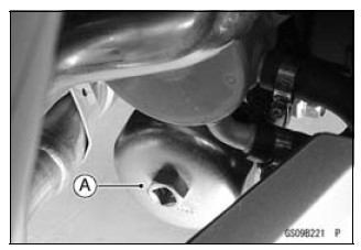
- Drain the engine oil (see Engine Oil Change).
- Remove the oil filter with the oil filter wrench [A].
Special Tool - Oil Filter Wrench: 57001-1249
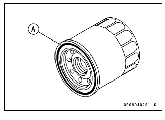
- Replace the filter with a new one.
- Apply grease to the gasket [A] before installation.
- Tighten the filter with the oil filter wrench.
Torque - Oil Filter: 17 N*m (1.7 kgf*m, 13 ft*lb)
NOTE
- Hand tightening of the oil filter can not be allowed since it does not reach to this tightening torque.
- Pour in the specified type and amount of oil (see Engine Oil Change).
Brake Hose Replacement
- Remove:
Upper Fairing (see Upper Fairing Removal in the Frame chapter)
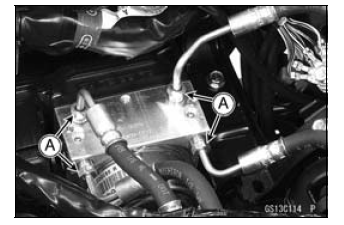
Brake Hose Fitting Bolt [A]
NOTICE Brake fluid quickly ruins painted plastic surfaces; any spilled fluid should be completely washed away immediately.
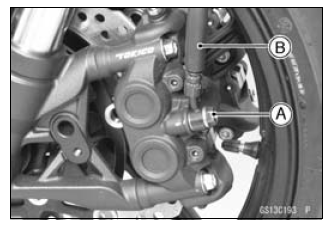
- Remove the brake hose banjo bolts [A].
- When removing the brake hose, take care not to spill the brake fluid on the painted or plastic parts.
- When removing the brake hoses [B], temporarily secure the end of the brake hose to some high place to keep fluid loss to a minimum.
- Immediately wash away any brake fluid that spills.
- There are washers on each side of the brake hose fitting.
- Replace them with new ones when installing.
- Fit the projection of the brake hose end to the calipers and master
cylinders, and tighten the brake hose banjo bolts to the specified torque.
Torque - Brake Hose Banjo Bolts: 25 N*m (2.5 kgf*m, 18 ft*lb)
- When installing the hoses, avoid sharp bending, kinking, flatting or twisting, and route the hoses according to Cable, Wire, and Hose Routing section in the Appendix chapter.
- Fill the brake line after installing the brake hose (see Brake Fluid Change).
- For ABS equipped models; note the following.
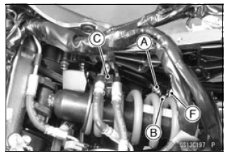
- Remove:
Air Cleaner Housing (see Air Cleaner Housing Removal in the Fuel System (DFI) chapter)
Battery Case (see Battery Case Removal in the Frame chapter)
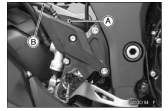
Brake Pipe Joint Nuts [A]
Bolts [B]
Clamps [C]
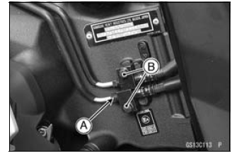
- Open the band [D].
- Clear the brake pipe from the holder [E].
- Remove the exhaust butterfly valve cable clamp [F].
- There are washers on each side of the brake hose fitting.
Replace them with new ones when installing.
- Before installing the brake pipe, check to see that there is no damage
on the threads of the brake pipe joint nut.
If there is any damage, replace the damaged parts with new ones.
NOTE
- Hand tighten the brake pipe joint nuts at both ends of the brake pipe temporarily and then tighten them to the specified torque.
- Tighten the brake pipe joint nuts with the flare nut wrench.
- Tighten:
Torque -
Brake Hose Banjo Bolts: 25 N*m (2.5 kgf*m, 18 ft*lb)
Brake Pipe Joint Nuts: 18 N*m (1.8 kgf*m, 13 ft*lb)
- When installing the hoses, avoid sharp bending, kinking, flatting or twisting, and route the hoses according to Cable, Wire, and Hose Routing section in the Appendix chapter.
- Fill the brake line after installing the brake hose (see Brake Fluid Change).
Brake Fluid Change
NOTE
- The procedure to change the front brake fluid is as follows.
Changing the rear brake fluid is the same as for the front brake.
- Level the brake fluid reservoir.
- Remove the reservoir cap.
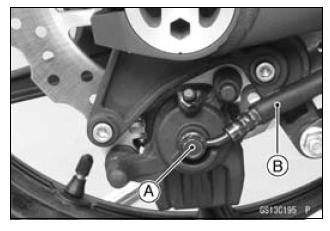
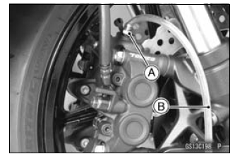
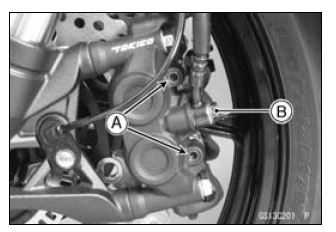
- Remove the rubber cap from the bleed valve [A] on the caliper.
- Attach a clear plastic hose [B] to the bleed valve, and run the other end of the hose into a container.
- Fill the reservoir with fresh specified brake fluid.
- Change the brake fluid.
- Repeat this operation until fresh brake fluid comes out from the plastic hose or the color of the fluid changes.
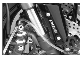
1. Open the bleed valve [A].
2. Apply the brake and hold it [B].
3. Close the bleed valve [C].
4. Release the brake [D].
NOTE
- The fluid level must be checked often during the changing operation and replenished with fresh brake fluid. If the fluid in the reservoir runs out any time during the changing operation, the brakes will need to be bled since air will have entered the brake line.
- Front Brake: Repeat the above steps for the other caliper.
- Tighten:
Torque - Front Master Cylinder Reservoir Stopper Screw: 1.2 N*m (0.12 kgf*m, 11 in*lb)
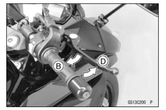
- Follow the procedure below to install the front/rear brake fluid
reservoir cap correctly.
- First, tighten the rear brake fluid reservoir cap [B] clockwise [C] by hand until slight resistance is felt indicating that the cap is seated on the reservoir body, then tighten the cap an additional 1/6 turn [D] while holding the brake fluid reservoir body [A].
- Tighten the bleed valve, and install the rubber cap.
Torque - Bleed Valves: 7.8 N*m (0.80 kgf*m, 69 in*lb)
- After changing the fluid, check the brake for good braking power, no
brake drag, and no fluid leakage.
If necessary, bleed the air from the lines.
Master Cylinder Rubber Parts Replacement
Front Master Cylinder Disassembly
- Remove the front master cylinder (see Front Master Cylinder
- Removal in the Brakes chapter).
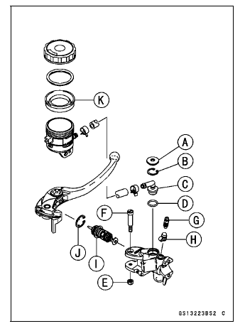
- Remove the seal cover [A], circlip [B], connector [C] and O-ring [D].
Special Tool - Inside Circlip Pliers: 57001-143
- Unscrew the locknut [E] and pivot bolt [F], and remove the brake lever.
- Remove the bleed valve [G] and rubber cap [H].
- Remove the piston assembly [I] as follows.
- Remove the dust cover and push rod.
- Remove the circlip [J].
- Pull out the piston (with primary cup and secondary cup).
- Remove the return spring and spring guide.
- Replace:
- Seal Cover [A]
- Circlip [B]
- O-ring [D]
- Rubber Cap [H]
- Piston Assembly [I]
- Circlip [J]
- Diaphragm [K]
Rear Master Cylinder Disassembly
- Remove the rear master cylinder (see Rear Master Cylinder Removal in the Brakes chapter).
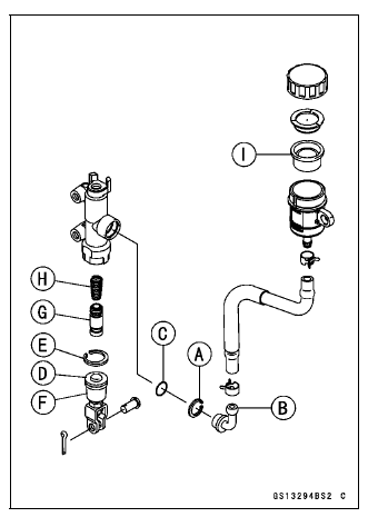
- Remove the circlip [A], connector [B] and O-ring [C].
Special Tool - Inside Circlip Pliers: 57001-143
- Slide the dust cover [D] out of place, and remove the circlip [E].
- Pull out the push rod assy [F].
- Take off the piston assy [G] and return spring [H].
NOTICE Do not remove the secondary cup from the piston since removal will damage it.
- Replace:
- Circlip [A]
- O-ring [C]
- Circlip [E]
- Push Rod Assy [F]
- Piston Assy [G]
- Diaphragm [I]
Master Cylinder Assembly
- Before assembly, clean all parts including the master cylinder with brake fluid or alcohol.
NOTICE Except for the disc pads and disc, use only disc brake fluid, isopropyl alcohol, or ethyl alcohol for cleaning brake parts. Do not use any other fluid for cleaning these parts. Gasoline, engine oil, or any other petroleum distillate will cause deterioration of the rubber parts. Oil spilled on any part will be difficult to wash off completely, and will eventually deteriorate the rubber used in the disc brake.
- Apply brake fluid to the new parts and to the inner wall of the cylinder.
- Take care not to scratch the piston or the inner wall of the cylinder.
- For the front master cylinder, apply a non-permanent locking agent to the reservoir screw and bolt.
- Apply silicone grease to the contact portion of the push rod and brake lever pivot bolt.
- Tighten:
Torque -
Brake Lever Pivot Bolt: 1.0 N*m (0.10 kgf*m, 8.8 in*lb)
Brake Lever Pivot Bolt Locknut: 5.9 N*m (0.60 kgf*m, 52 in*lb)
Caliper Rubber Parts Replacement
Front Caliper Disassembly
- Loosen the front caliper pad pins [A] and banjo bolt [B] and tighten them loosely.
- Remove:
Front Caliper (see Front Caliper Removal in the Brakes chapter)
Brake Pads (see Front Brake Pad Removal in the brakes chapter)
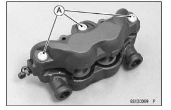
- Remove:
Front Caliper Assembly Bolts [A] - Split the front caliper.
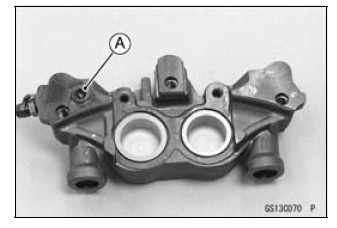
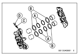
- Remove:
Pad Spring
O-ring [A]
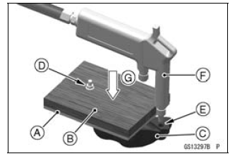
- Using compressed air, remove the pistons. One way to remove the pistons
is as follows.
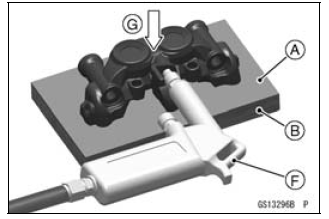
- Install a rubber gasket [A] and a wooden board [B] more than 10 mm (0.4 in.) thick on the caliper half.
- For inside caliper half [C], fasten them together with a suitable bolt and nut [D] as shown. Leave one of the oil passage [E] open.
- Lightly apply compressed air [F] to the oil passage until the
pistons hit the rubber gasket.
Push down [G]
WARNING The piston in the brake caliper can crush hands and fingers. Never place your hand or fingers in front of the piston.
- Pull out the pistons by hand.
- Remove the dust seals [A] and fluid seals [B].
- Remove the bleed valve [C] and rubber cap [D].
- Repeat the previous step to remove the pistons from the other side of the caliper body.
NOTE
- If compressed air is not available, do as follows for both calipers coincidentally, with the brake hose connected to the caliper.
- Prepare a container for brake fluid, and perform the work above it.
- Remove the pad springs and pads (see Front Brake Pad Removal in the Brakes chapter).
- Pump the brake lever until the pistons come out of the cylinders, and then disassemble the caliper.
Front Caliper Assembly
- Clean the caliper parts except for the pads.
NOTICE For cleaning the parts, use only disc brake fluid, isopropyl alcohol, or ethyl alcohol.
- Install the bleed valve and rubber cap.
Torque - Bleed Valves: 7.8 N*m (0.80 kgf*m, 69 in*lb)
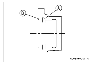
- Replace the fluid seals [A] with new ones.
- Apply silicone grease to the fluid seals, and install them into the cylinders by hand.
- Replace the dust seals [B] with new ones if they are damaged.
- Apply silicone grease to the dust seals, and install them into the cylinders by hand.
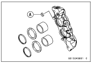
- Replace the O-ring [A] and install it.
- Apply brake fluid to the outside of the pistons, and push them into each cylinder by hand.
- Be sure to install the O-ring.
- Tighten:
Torque - Front Caliper Assembly Bolts: 22 N*m (2.2 kgf*m, 16 ft*lb)
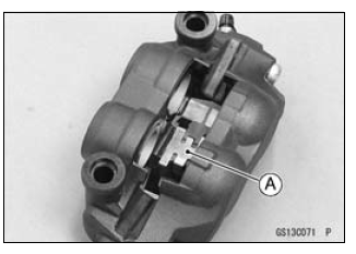
- Install the pad spring [A] as shown.
- Install the brake pads (see Front Brake Pad Installation in the Brakes chapter).
- Wipe up any spilled brake fluid on the caliper with wet cloth.
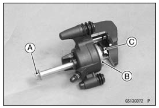
Rear Caliper Disassembly
- Remove:
Rear Caliper (see Rear Caliper Removal in the Brakes chapter)
Brake Pads (see Rear Brake Pad Removal in the Brakes chapter)
Caliper Holder - Using a rear caliper mounting bolt [A], screw the thread hole for banjo bolt to remove the piston [B].
- Remove the pad spring [C].
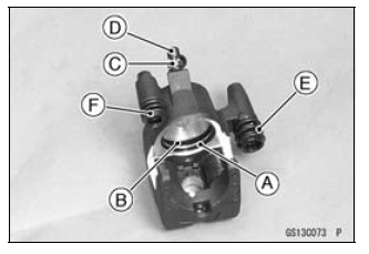
- Remove:
Dust Seal [A] and Fluid Seal [B]
Bleed Valve [C] and Rubber Cap [D]
Dust Boot [E]
Friction Boot [F]
Rear Caliper Assembly
- Clean the caliper parts except for the pads.
NOTICE For cleaning the parts, use only disc brake fluid, isopropyl alcohol, or ethyl alcohol.
- Install the bleed valve and rubber cap.
Torque - Bleed Valve: 7.8 N*m (0.80 kgf*m, 69 in*lb)
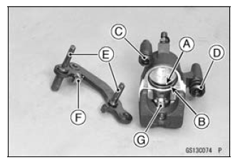
- Apply brake fluid to the cylinder bore.
- Replace the fluid seal [A] with a new one.
- Apply silicone grease to the fluid seal, and install it into the cylinder by hand.
- Replace the dust seal [B] with a new one.
- Apply brake fluid to the outside of the piston, and push it into the cylinder by hand as far as it will go.
- Replace the friction boot [C] and dust boot [D] with new ones.
- Apply silicone grease to the sliding surface of the caliper holder shafts [E].
- Check that the guide [F] is in place on the caliper holder.
- Install the pad spring [G].
- Install the pads (see Rear Brake Pad Installation in the Brakes chapter).
- Wipe up any spilled brake fluid on the caliper with wet cloth.
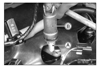
Spark Plug Replacement
- Remove the stick coils (see Stick Coil Removal in the Electrical System chapter).
- Remove the spark plugs [A] using the plug wrench [B] vertically.
Special Tool - Spark Plug Wrench, Hex 16: 57001-1262
- Replace the spark plug with a new one.
Standard Spark Plug
Type: NGK CR9EIA-9 - Insert new spark plug in the plug wrench.
- Using the plug wrench vertically, tighten the plug.
NOTICE The insulator of the spark plug may break if when the wrench is inclined during tightening.
Torque - Spark Plugs: 13 N*m (1.3 kgf*m, 115 in*lb)
- Install the stick coils securely.
- Be sure the stick coils are installed by pulling up it lightly.
See also:
 Kawasaki Z1000SX - Service manual > Others
Chassis Parts Lubrication Before lubricating each part, clean off any rusty spots with rust remover and wipe off any grease, oil, dirt, or grime. Lubricate the points listed below with indicated lubricant.
 Rider's Manual BMW R 1250 GS GSA
 Owner's Manual Harley-Davidson Sportster XL1200X Forty-Eight
 Owner's Manual Honda CBR650R
 Service manual Honda CBR650
 Owner's Manual Honda PCX125
 Owner's Manual Kawasaki Z1000SX
 Service manual Kawasaki Z1000SX
 Owner's Manual Lexmoto Echo
 Owner's Manual Royal Enfield Interceptor 650
 Service manual Royal Enfield Interceptor 650
 Owner's Manual Yamaha MT-07