 Honda CBR650 - Service manual > Secondary air supply system
SYSTEM INSPECTION
Start the engine and warm it up to normal operating temperature.
Stop the engine.
Lift the fuel tank and support it.
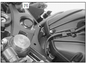
Disconnect the air supply hose [1] from the air cleaner housing.
Check that the hose joint (secondary air intake port) of the air cleaner housing is clean and free of carbon deposits.
Check the PAIR check valve if the port is carbon fouled.
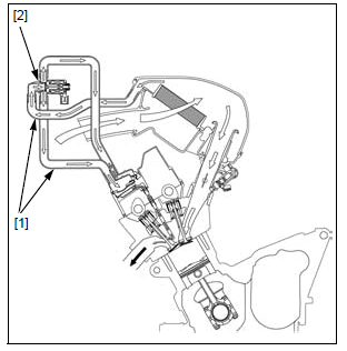
Start the engine and open the throttle slightly to be certain that air is sucked in through the disconnected air supply hose.
If the air is not drawn in, check the air supply hoses [1] for clogs and PAIR control solenoid valve [2].
Start the engine and open the throttle slightly to be certain that air is sucked in through the disconnected air supply hose.
If the air is not drawn in, check the air supply hoses [1] for clogs and PAIR control solenoid valve [2].
PAIR CONTROL SOLENOID VALVE REMOVAL/INSTALLATION
Remove the air cleaner housing.
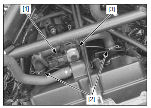
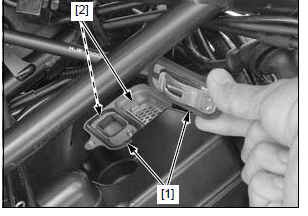
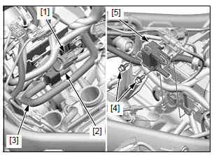
Disconnect the 2P (Black) connector [1].
Disconnect the air supply hoses [2] from the cylinder head cover and remove the PAIR control solenoid valve assembly [3].
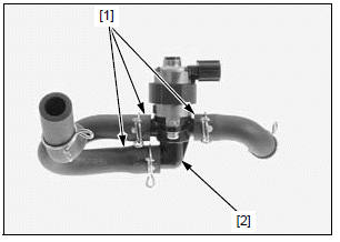
Disconnect the air supply hoses [1] from the PAIR control solenoid valve [2].
Installation is in the reverse order of removal.
PAIR CONTROL SOLENOID VALVE INSPECTION
Remove the PAIR control solenoid valve.
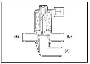
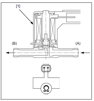
Check that air flows (A) to (B) when the 12 V battery is connected to the PAIR control solenoid valve terminals.
Air should not flow (A) to (B) when the battery is disconnected.
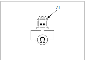
Measure the resistance between the 2P connector [1] terminals of the PAIR control solenoid valve.
STANDARD: 23 - 27 Ω (20ºC/68ºF)
If the resistance is out of the specification, replace the PAIR control solenoid valve.
PAIR CHECK VALVE REMOVAL/ INSTALLATION
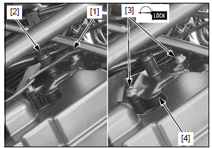
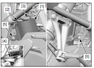
Pull off the heat guard rubber [1] from the check valve cover joint [2].
Remove the two bolts [3] and check valve cover [4].
Remove the PAIR check valves [1] and baffle plates [2].
Installation is in the reverse order of removal.
NOTE:
- Apply locking agent to the threads of the PAIR check valve cover bolt.
TORQUE:
PAIR check valve cover bolt:
12 N*m (1.2 kgf*m, 9 lbf*ft)
PAIR CHECK VALVE INSPECTION
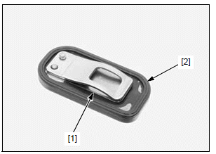
Remove the PAIR check valves.
Check the reed [1] of the PAIR check valve for damage or fatigue. Replace if necessary.
Replace the PAIR check valve if the rubber seat [2] is cracked, deteriorated or damaged, or if there is clearance between the reed and seat.
EVAP purge control solenoid valve (TH model only)
REMOVAL/INSTALLATION
Remove the throttle body.
Disconnect the following:
- EVAP purge control solenoid valve 2P (Black) connector [1]
- Canister-to-EVAP purge control solenoid valve hose [2]
- EVAP vacuum hose [3]
Remove the two bolts [4] and EVAP purge control solenoid valve [5].
Installation is in the reverse order of removal.
INSPECTION
Remove the EVAP purge control solenoid valve [1].
Check that air flows (A) to (B) when the 12 V battery is connected to the EVAP purge control solenoid valve terminals. Air should not flow (A) to (B) when the battery is disconnected.
Check the resistance between the terminals of the EVAP purge control solenoid valve.
STANDARD: 30 - 34 Ω (20ºC/68ºF)
If the resistance is out of specification, replace the EVAP purge control solenoid valve.
EVAP canister (TH model only)
REMOVAL/INSTALLATION
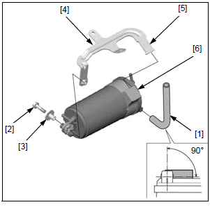
Disconnect the following from the EVAP canister [1]:
- Fuel tank-to-EVAP canister hose [2]
- Canister-to-EVAP purge control solenoid valve hose [3]
- EVAP canister drain hose [4]
Remove the two mounting bolts [5] and EVAP canister.
Disconnect the EVAP canister breather hose [1].
Remove the bolt [2] and collar [3].
Remove the EVAP canister stay [4] by releasing the tab [5] from the groove of the rubber mount [6].
Installation is in the reverse order of removal.
See also:
 Honda CBR650 - Service manual > Fuel injector
REMOVAL/INSTALLATION Remove the air cleaner housing. Disconnect the fuel injector 2P (Black) connectors [1] Remove the following: Four bolts [2] Fuel rails/joint [3] and fuel injectors [4] (as an assembly) Fuel injectors [1] Seal rings [2] O-rings [3] Fuel rails [1] Fuel rail joint [2] O-rings [3]
 Rider's Manual BMW R 1250 GS GSA
 Owner's Manual Harley-Davidson Sportster XL1200X Forty-Eight
 Owner's Manual Honda CBR650R
 Service manual Honda CBR650
 Owner's Manual Honda PCX125
 Owner's Manual Kawasaki Z1000SX
 Service manual Kawasaki Z1000SX
 Owner's Manual Lexmoto Echo
 Owner's Manual Royal Enfield Interceptor 650
 Service manual Royal Enfield Interceptor 650
 Owner's Manual Yamaha MT-07