 Kawasaki Z1000SX - Service manual > Self-Diagnosis
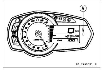
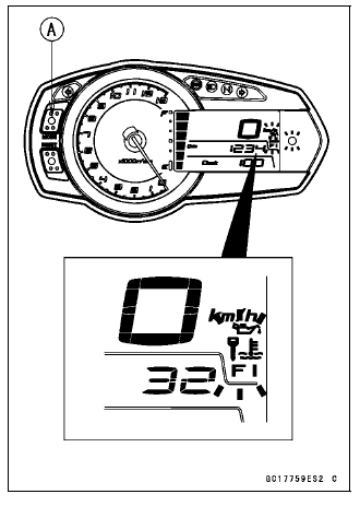
The warning indicator light (LED) [A] is used for the FI indicator, immobilizer indicator (equipped models) and oil pressure warning indicator.
Self-diagnosis Outline
The self-diagnosis system has two modes and can be switched to another mode by operating the meter unit.
User Mode
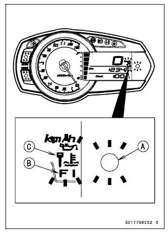
The ECU notifies the rider of troubles in DFI system, ignition system and immobilizer system by blinking the warning indicator light (LED) [A], FI warning symbol [B] and immobilizer warning symbol [C] when DFI, ignition and immobilizer system parts are faulty, and initiates fail-safe function. In case of serious troubles ECU stops the injection and ignition operations.

Dealer Mode
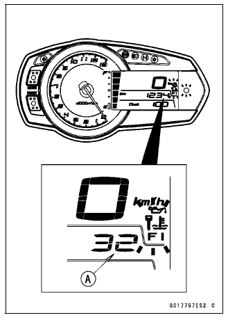
The LCD (Liquid Crystal Display) display the service code(s) [A] to show the problem(s) which the DFI system, ignition system and immobilizer system has at the moment of diagnosis.
Self-diagnosis Procedures
- When a problem occurs with the DFI system and ignition system, the warning indicator light (LED) [A] and FI warning symbol [B] blink.
- For models equipped with an immobilizer system, when a problem occurs with the system, the warning indicator light (LED) and immobilizer warning symbol [C] blink.
NOTE
- Use a fully charged battery when conducting self-diagnosis. Otherwise, the light (LED) and symbol blink very slowly or do not blink.
- Turn the ignition switch ON.
- Push the MODE button [A] to display the odometer.
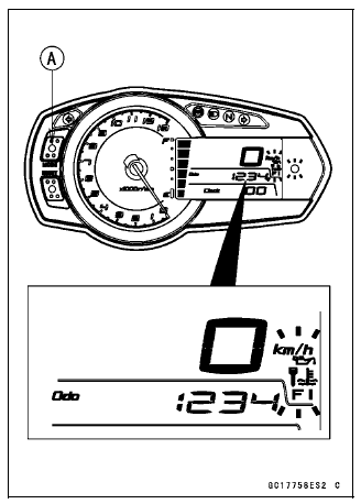
- Push the MODE button [A] for more than two seconds.
- The service code [B] is displayed on the LCD by the number of two digits.
- Any of the following procedures ends self-diagnosis.
- When the service code is displayed on the LCD, push the left button for more than two seconds.
- When the ignition switch is turned OFF.
Self-Diagnosis Flow Chart
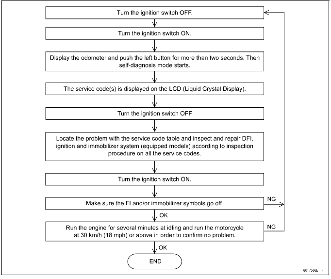
Self-Diagnosis
Service Code Reading
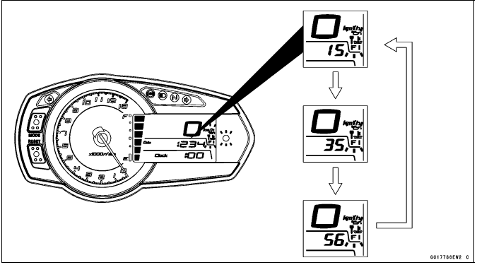
- The service code(s) is displayed on the LCD by the number of two digits.
- When there are a number of problems, all the service codes can be stored and the display will begin starting from the lowest number service code in the numerical order.
- Then after completing all codes, the display is repeated until the ignition switch is turned OFF or MODE button is pushed for more than two seconds.
- For example, if three problems occurred in the order of 56, 15, 35, the
service codes are displayed (each two seconds) from the lowest number in the
order listed as shown below.
(15→35→56)→(15→35→56)→* * *(repeated)
- If there is no problem or when the repair has been done, FI and/or immobilizer symbols go off and service code is not displayed.
Service Code Erasing
- When repair has been done, FI and/or immobilizer warning symbols go off
and service code is not displayed.
But the service codes stored in memory of the ECU are not erased to preserve the problem history.
In this model, the problem history can not be erased.
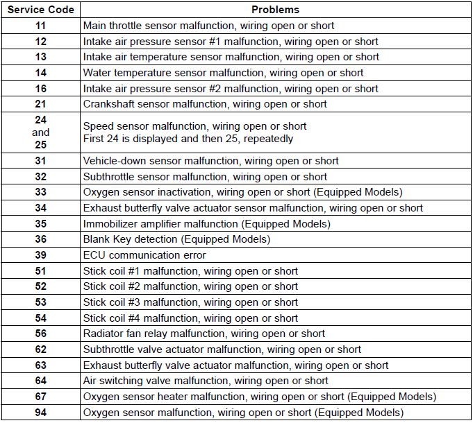
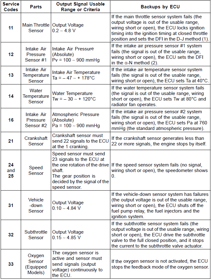
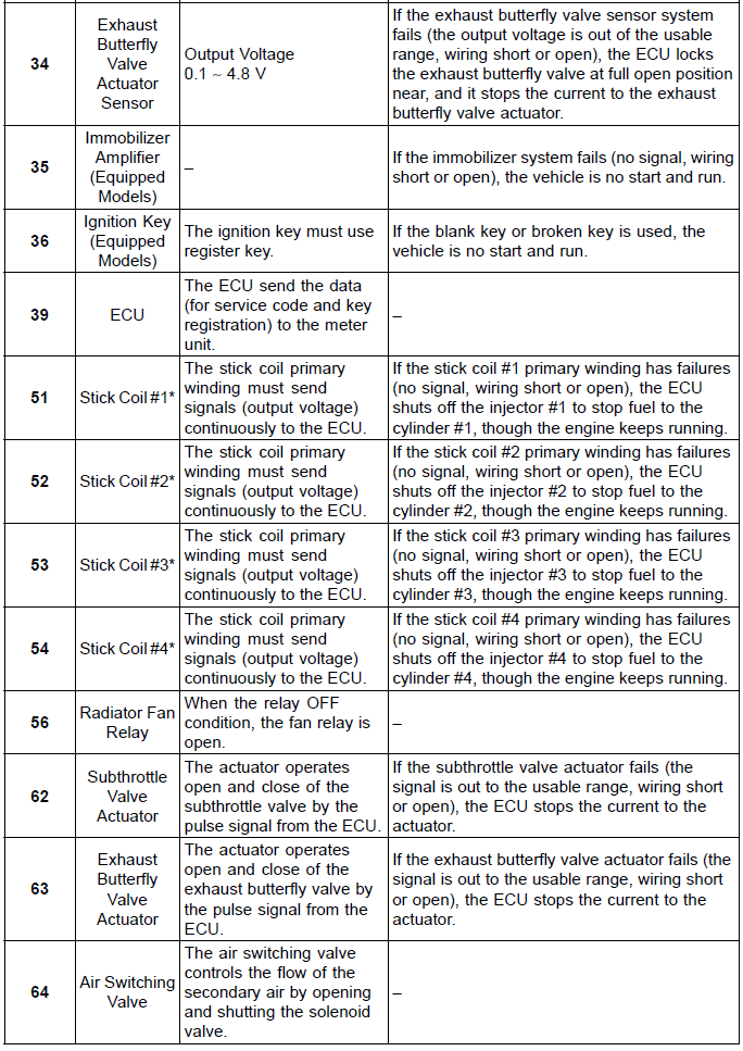
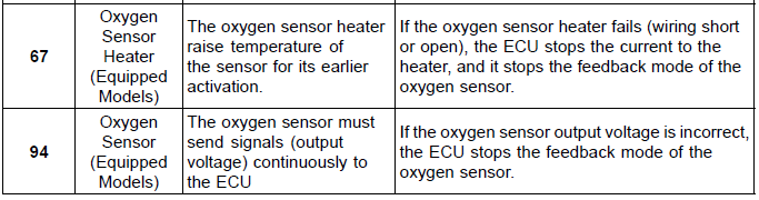
Service Code Table
Notes:
- The ECU may be involved in these problems. If all the parts and circuits checked out good, be sure to check the ECU for ground and power supply. If the ground and power supply are checked good, replace the ECU.
- When no service code is displayed, the electrical parts of the DFI system has no fault, and the mechanical parts of the DFI system and the engine are suspect.
Backups
- The ECU takes the following measures to prevent engine damage when the DFI, ignition or immobilizer system parts have troubles.
Note:
- D-J Method: The DFI control method from medium to heavy engine load. When the engine load is light like at idling or low speed, the ECU determines the injection quantity by calculating from the throttle vacuum (intake air pressure sensor output voltage) and engine speed (crankshaft sensor output voltage). This method is called D-J method.
- α-N Method: As the engine speed increases, and the engine load turns middle to heavy, the ECU determines the injection quantity by calculating from the throttle opening (main throttle sensor output voltage) and the engine speed. This method is called α-N method.
*: This depends on the number of stopped cylinders.
See also:
 Kawasaki Z1000SX - Service manual > Troubleshooting the DFI System
The warning indicator light (LED) [A] is used for the FI indicator, immobilizer indicator (equipped models) and oil pressure warning indicator.
Kawasaki Z1000SX - Service manual > Main Throttle Sensor (Service Code 11)
The main throttle sensor is a rotating variable resistor that change output voltage according to throttle operating. The ECU senses this voltage change and determines fuel injection quantity, and ignition timing according to engine rpm, and throttle opening.
 Rider's Manual BMW R 1250 GS GSA
 Owner's Manual Harley-Davidson Sportster XL1200X Forty-Eight
 Owner's Manual Honda CBR650R
 Service manual Honda CBR650
 Owner's Manual Honda PCX125
 Owner's Manual Kawasaki Z1000SX
 Service manual Kawasaki Z1000SX
 Owner's Manual Lexmoto Echo
 Owner's Manual Royal Enfield Interceptor 650
 Service manual Royal Enfield Interceptor 650
 Owner's Manual Yamaha MT-07