 Kawasaki Z1000SX - Service manual > Troubleshooting the DFI System
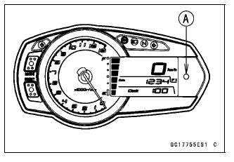
The warning indicator light (LED) [A] is used for the FI indicator, immobilizer indicator (equipped models) and oil pressure warning indicator.
Outline
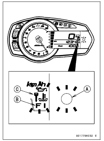
When a problem occurs with DFI system, the warning indicator light (LED) [A] and FI warning symbol [B] blinks to alert the rider. In addition, the condition of the problem is stored in the memory of the ECU. For models equipped with an immobilizer system, the warning indicator light (LED) and immobilizer warning symbol [C] blinks, when a problem occurs in the system.
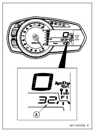
With the engine stopped and turned in the self-diagnosis mode, the service code [A] is displayed on the LCD (Liquid Crystal Display) by the number of two digits.
If the problem is with the following parts, the ECU can not recognize these problem. Therefore, the warning indicator light (LED), FI and/or immobilizer warning symbols do not blinks, and service code is not displayed.
LCD for Meter Unit
Fuel Pump
Fuel Pump Relay
Fuel Injectors
Stick Coil Secondary Wiring and Ground Wiring
ECU Main Relay
ECU Power Source Wiring and Ground Wiring
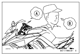
When the service code [A] is displayed, for first ask the rider about the conditions [B] of trouble, and then start to determine the cause [C] of problem.
As a pre-diagnosis inspection, check the ECU for ground and power supply, the fuel line for no fuel leaks, and for correct pressure. The pre-diagnosis items are not indicated by the warning indicator light (LED) and FI warning symbol.
Don't rely solely on the DFI self-diagnosis function, use common sense.
Even when the DFI system is operating normally, the warning indicator light (LED) and FI warning symbol may blink under strong electrical interference. Additional measures are not required. Turn the ignition switch OFF to stop the indicator light and symbol.
If the warning indicator light (LED) and FI warning symbol of the motorcycle brought in for repair still blinks, check the service code.
When the repair has been done, the FI warning symbol goes off. But the service codes stored in memory of the ECU are not erased to preserve the problem history. The problem history can be referred using the KDS (Kawasaki Diagnostic System) when solving unstable problems.
When the motorcycle is down, the vehicle-down sensor operates and the ECU shuts off the fuel pump relay, fuel injectors and ignition system. The ignition switch is left ON. If the starter button is pushed, the electric starter turns but the engine does not start. When the starter button is pushed, the warning indicator light (LED) and FI warning symbol blink but the service code is not displayed. To start the engine again, raise the motorcycle, turn the ignition switch OFF, and then ON.
Much of the DFI system troubleshooting work consists of confirming continuity of the wiring. The DFI parts are assembled and adjusted with precision, and it is impossible to disassemble or repair them.
- When checking the DFI parts, use a digital meter which can be read two
decimal place voltage or resistance.
- The DFI part connectors [A] have seals [B], including the ECU. When measuring the input or output voltage with the connector joined, use the needle adapter set [C]. Insert the needle adapter inside the seal until the needle adapter reaches the terminal.
Special Tool - Needle Adapter Set: 57001-1457
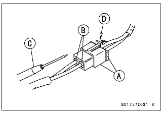
NOTICE Insert the needle adapter straight along the terminal in the connector to prevent short-circuit between terminals.
- Make sure that measuring points are correct in the connector, noting the position of the lock [D] and the lead color before measurement. Do not reverse connections of a digital meter.
- Be careful not to short-circuit the leads of the DFI or electrical system parts by contact between adapters.
- Turn the ignition switch ON and measure the voltage with the connector joined.
NOTICE Incorrect, reverse connection or short circuit by needle adapters could damage the DFI or electrical system parts.
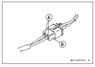
- After measurement, remove the needle adapters and apply silicone sealant to the seals [A] of the connector [B] for waterproofing.
Sealant - Liquid Gasket, TB1211: 56019-120
- Always check battery condition before replacing the DFI parts. A fully charged battery is a must for conducting accurate tests of the DFI system.
- Trouble may involve one or in some cases all items.
Never replace a defective part without determining what CAUSED the problem. If the problem was caused by some other item or items, they too must be repaired or replaced, or the new replacement part will soon fail again.
- Measure coil winding resistance when the DFI part is cold (at room temperature).
- Make sure all connectors in the circuit are clean and tight, and examine
leads for signs of burning, fraying, short, etc. Deteriorated leads and bad
connections can cause reappearance of problems and unstable operation of the
DFI system.
If any wiring is deteriorated, replace the wiring.
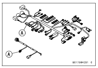
- Pull each connector [A] apart and inspect it for corrosion, dirt, and
damage.
If the connector is corroded or dirty, clean it carefully. If it is damaged, replace it. Connect the connectors securely.
- Check the wiring for continuity.
- Use the wiring diagram to find the ends of the lead which is suspected of being a problem.
- Connect the hand tester between the ends of the leads.
Special Tool - Hand Tester: 57001-1394
- Set the tester to the × 1 Ω range, and read the tester.
If the tester does not read 0 Ω, the lead is defective. Replace the lead or the main harness or the subharness.
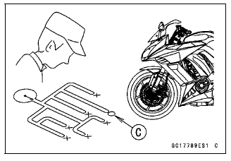
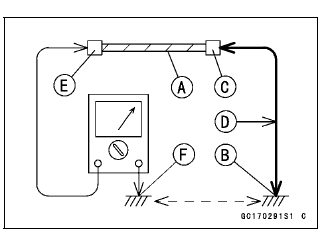
- If both ends of a harness [A] are far apart, ground [B] the one end [C], using a jumper lead [D] and check the continuity between the end [E] and the ground [F]. This enables to check a long harness for continuity. If the harness is open, repair or replace the harness.
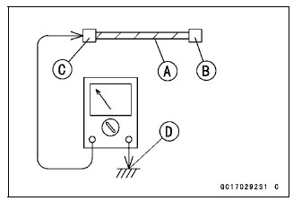
- When checking a harness [A] for short circuit, open one end [B] and check the continuity between the other end [C] and ground [D]. If there is continuity, the harness has a short circuit to ground, and it must be repaired or replaced.
- Narrow down suspicious locations by repeating the continuity tests from
the ECU connectors.
If no abnormality is found in the wiring or connectors, the DFI parts are the next likely suspects. Check the part, starting with input and output voltages. However, there is no way to check the ECU itself.
If an abnormality is found, replace the affected DFI part.
If no abnormality is found in the wiring, connectors, and DFI parts, replace the ECU.
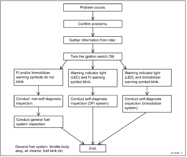
DFI Diagnosis Flow Chart
Inquiries to Rider
- Each rider reacts to problems in different ways, so it is important to confirm what kind of symptoms the rider has encountered.
- Try to find out exactly what problem occurred under exactly what conditions by asking the rider; knowing this information may help you reproduce the problem.
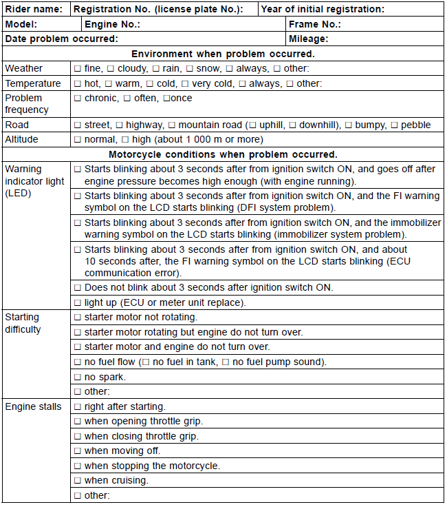
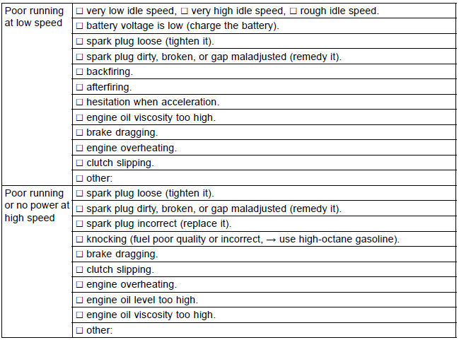
- The following sample diagnosis sheet will help prevent you from overlooking any areas, and will help you decide if it is a DFI system problem, or a general engine problem.
Sample Diagnosis Sheet
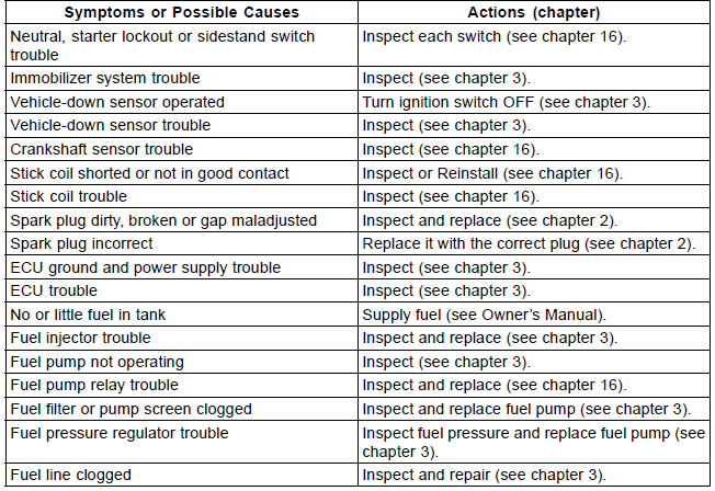
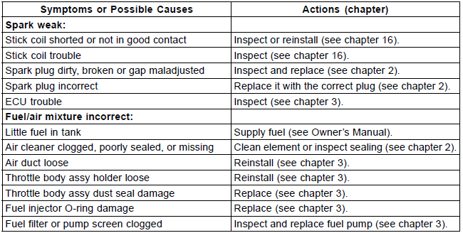
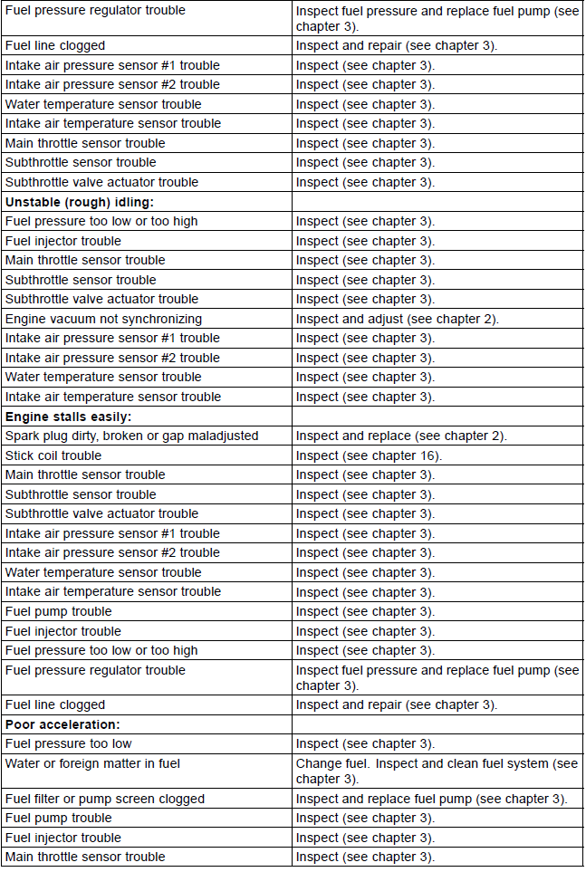
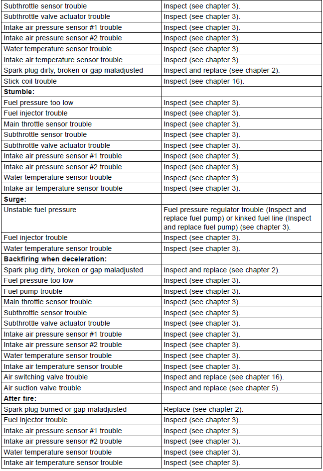
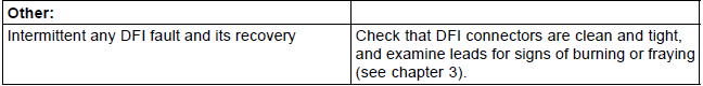
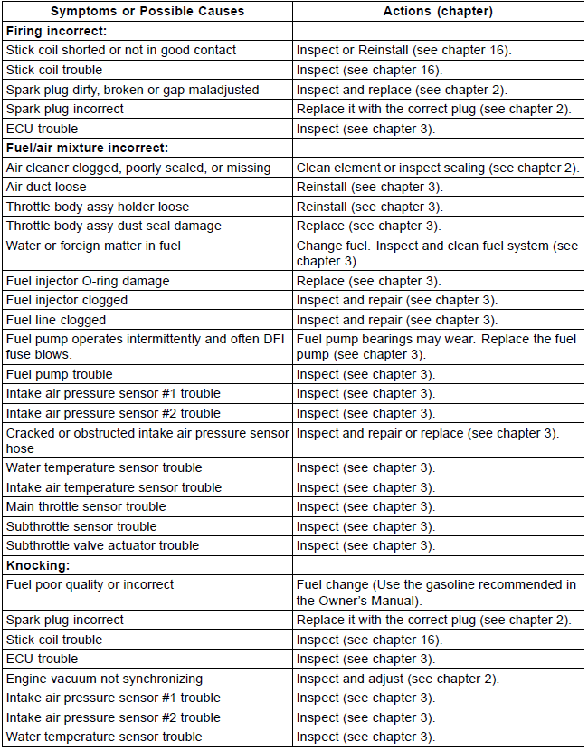
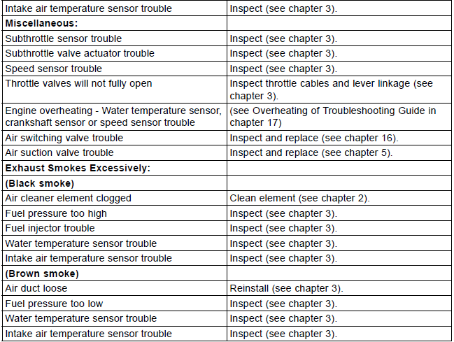
DFI System Troubleshooting Guide
NOTE
- This is not an exhaustive list, giving every possible cause for each problem listed. It is meant simply as a rough guide to assist the troubleshooting for some of the more common difficulties in DFI system.
- The ECU may be involved in the DFI electrical and ignition system troubles. If these parts and circuits are checked out good, be sure to check the ECU for ground and power supply. If the ground and power supply are checked good, replace the ECU.
Engine Won't Turn Over
Poor Running at Low Speed
Poor Running or No Power at High Speed
See also:
 Kawasaki Z1000SX - Service manual > DFI Parts Location, DFI Servicing Precautions
DFI Parts Location Main Throttle Sensor [A] Subthrottle Sensor [B]
Kawasaki Z1000SX - Service manual > Self-Diagnosis
The warning indicator light (LED) [A] is used for the FI indicator, immobilizer indicator (equipped models) and oil pressure warning indicator.
 Rider's Manual BMW R 1250 GS GSA
 Owner's Manual Harley-Davidson Sportster XL1200X Forty-Eight
 Owner's Manual Honda CBR650R
 Service manual Honda CBR650
 Owner's Manual Honda PCX125
 Owner's Manual Kawasaki Z1000SX
 Service manual Kawasaki Z1000SX
 Owner's Manual Lexmoto Echo
 Owner's Manual Royal Enfield Interceptor 650
 Service manual Royal Enfield Interceptor 650
 Owner's Manual Yamaha MT-07