 Honda CBR650 - Service manual > Service information
GENERAL
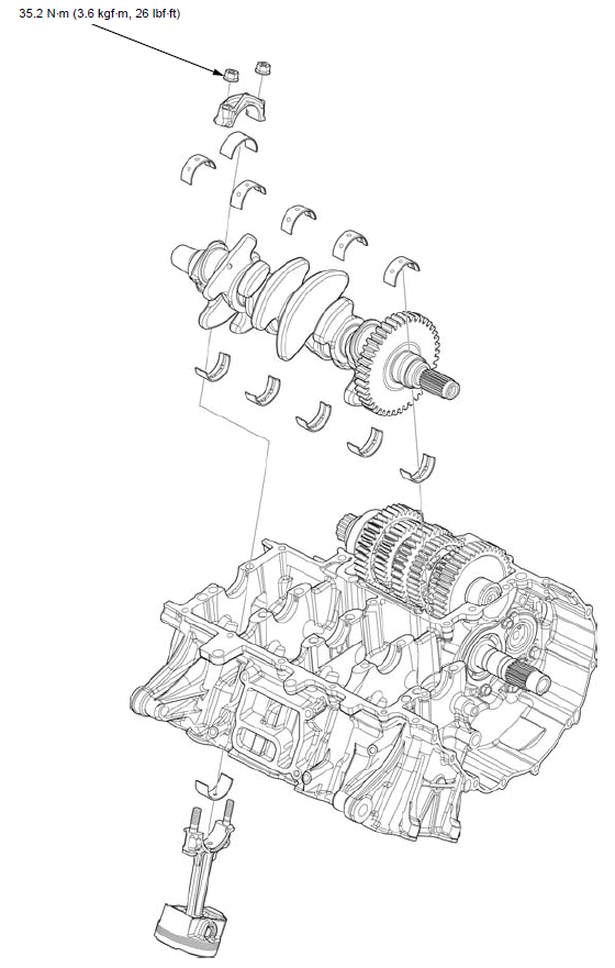
- The crankcase must be separated to service the crankshaft, cylinder, piston/connecting rod and piston oil jet. Refer to procedures for crankcase separation.
- Mark and store the connecting rods, bearing caps and bearing inserts to be sure of their correct locations for reassembly.
- The crankpin and main journal bearing inserts are select fit and are identified by color codes. Select replacement bearings from the code tables. After selecting new bearings, recheck the oil clearance with a plastigauge. Incorrect oil clearance can cause major engine damage.
Troubleshooting
Cylinder compression is too low, hard to starting or poor performance at low speed
- Leaking cylinder head gasket
- Worn, stuck or broken piston ring
- Worn or damaged cylinder and piston
Cylinder compression too high, overheating or knocking
- Excessive carbon built-up on piston head or combustion chamber
Excessive smoke
- Worn cylinder, piston or piston ring
- Improper installation of piston rings
- Scored or scratched piston or cylinder wall
Abnormal noise
- Worn piston pin or piston pin hole
- Worn connecting rod small end
- Worn cylinder, piston or piston rings
- Worn main journal bearings
- Worn crankpin bearings
Engine vibration
- Excessive crankshaft runout
Component location
Crankshaft
SIDE CLEARANCE INSPECTION
Separate the crankcase halves.
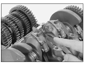
Measure the connecting rod side clearance.
SERVICE LIMIT: 0.25 mm (0.010 in)
If the clearance exceeds the service limit, replace the connecting rod.
Recheck and if still out of limit, replace the crankshaft.
REMOVAL
NOTICE
Do not interchange the bearing inserts. They must be installed in their original locations or the correct bearing oil clearance may not be obtained, resulting in engine damage.
Separate the crankcase halves.
Mark the bearing caps and bearings as you remove them to indicate the correct cylinder for reassembly.
Be careful not to damage the crankpin, main journal and bearing inserts.
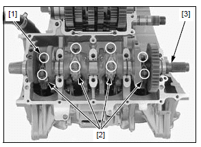
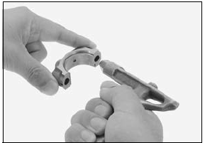
Remove the crankpin bearing cap nuts [1] and bearing caps [2].
- Tap the side of the cap lightly if the bearing cap is hard to remove.
Remove the crankshaft [3].
NOTICE
Before removal, position all the pistons at TDC (Top Dead Center) to prevent damaging the crankpin with the connecting rod.
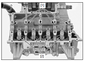
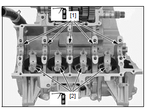
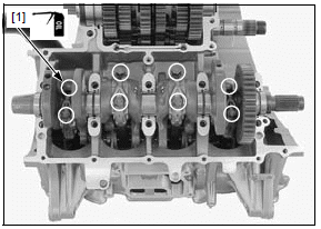
Remove the main journal bearings [1] from both crankcase halves.
Remove the crankpin bearings [2] from the connecting rods and bearing caps.
NOTICE
Do not interchange the bearing inserts. They must be installed in their original locations or the correct bearing oil clearance may not be obtained, resulting in engine damage.
INSPECTION
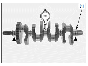
Support the crankshaft [1] on both end journals.
Set a dial gauge on the center main journal of the crankshaft avoiding the oil groove and hole.
Rotate the crankshaft two revolutions (720º) and read the runout.
SERVICE LIMIT: 0.05 mm (0.002 in)
INSTALLATION
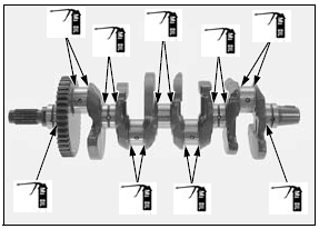
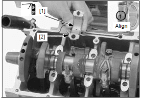
Apply molybdenum oil solution to the main journal bearing [1] sliding surfaces on the upper crankcase and crankpin bearing [2] sliding surfaces on the connecting rods.
The bearing tabs should be aligned with the grooves in the crankcase.
Install the main journal bearings and crankpin bearings in the original locations.
NOTICE
Do not interchange the bearing inserts. they must be installed in their original locations or the correct bearing oil clearance may not be obtained, resulting in engine damage.
Apply molybdenum oil solution to the thrust surfaces of the crankshaft as shown.
NOTICE
Position all the pistons at TDC (Top Dead Center) to prevent damaging the crankpin with the connecting rod.
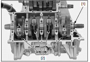
Install the crankshaft [1] onto the upper crankcase.
Set the connecting rods [2] onto the crankpins.
Clean the mating surface of the connecting rods and crankpin bearing caps with solvent and blow them with compressed air.
Apply molybdenum oil solution to the crankpin bearing [1] sliding surfaces on the crankpin bearing caps [2].
Install the crankpin bearing caps by aligning the I.D.
code number on the connecting rod and bearing cap.
NOTICE
Be sure to install each part in its original position, as noted during removal.
Apply engine oil to the crankpin bearing cap nut [1] threads and seating surfaces.
Install and tighten the crankpin bearing cap nuts in 2 or 3 steps alternately to the specified torque.
TORQUE:35.2 N*m (3.6 kgf*m, 26 lbf*ft)
Assemble the crankcase halves.
See also:
 Honda CBR650 - Service manual > Main journal bearing
NOTICE Do not interchange the bearing inserts. They must be installed in their original locations or the correct bearing oil clearance may not be obtained, resulting in engine damage.
 Rider's Manual BMW R 1250 GS GSA
 Owner's Manual Harley-Davidson Sportster XL1200X Forty-Eight
 Owner's Manual Honda CBR650R
 Service manual Honda CBR650
 Owner's Manual Honda PCX125
 Owner's Manual Kawasaki Z1000SX
 Service manual Kawasaki Z1000SX
 Owner's Manual Lexmoto Echo
 Owner's Manual Royal Enfield Interceptor 650
 Service manual Royal Enfield Interceptor 650
 Owner's Manual Yamaha MT-07