 Honda CBR650 - Service manual > Main journal bearing
NOTICE
Do not interchange the bearing inserts. They must be installed in their original locations or the correct bearing oil clearance may not be obtained, resulting in engine damage.
BEARING INSPECTION
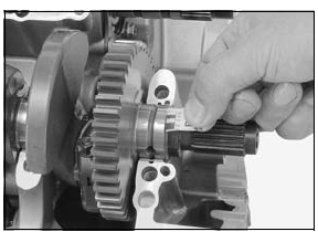
Remove the crankshaft.
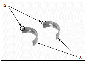
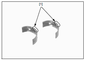
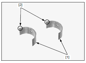
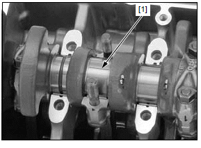
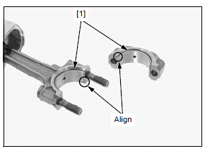
Check the main journal bearing inserts [1] for unusual wear or peeling.
Check the bearing tabs [2] for damage.
If the main journal bearing is damaged, select a replacement bearing.
OIL CLEARANCE INSPECTION
Remove the crankshaft.
Clean off any oil from the bearing inserts and main journals.
Install the crankshaft onto the upper crankcase.
Do not rotate the crankshaft during inspection.
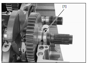
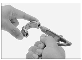
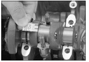
Put a strip of plastigauge [1] lengthwise on each main journal avoiding the oil hole.
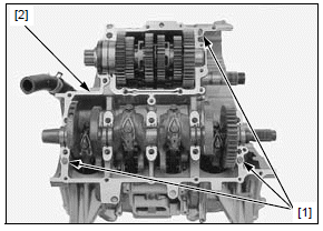
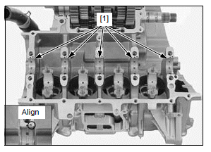
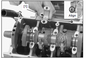
Install the dowel pins [1] onto the upper crankcase [2].
Install the lower crankcase onto the upper crankcase.
Clean the crankcase main journal bolts (reuse) in solvent, and dry them thoroughly.
Apply engine oil to the crankcase main journal bolt threads and seating surfaces.
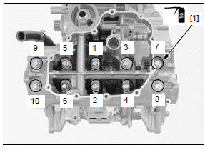
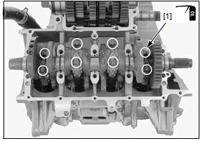
Install the crankcase main journal bolts [1].
Make sure the upper and lower crankcase are seated securely.
Tighten the crankcase main journal bolts in numerical order as shown in a crisscross pattern in 2 or 3 steps to the specified torque.
Further tighten the crankcase main journal bolts 120º.
TORQUE:15 N*m (1.5 kgf*m, 11 lbf*ft) + 120º
Remove the crankcase main journal bolt and lower crankcase.
Measure the compressed plastigauge at its widest point on each main journal to determine the oil clearance.
SERVICE LIMIT: 0.05 mm (0.002 in)
If the oil clearance exceeds the service limit, select a replacement bearing.
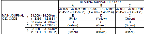
BEARING SELECTION
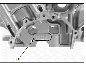
Letters (A, B or C) on the left side of upper crankcase are bearing support I.D. codes from left to right.
Record the crankcase bearing support I.D. code letters [1] from left side of the upper crankcase as shown.
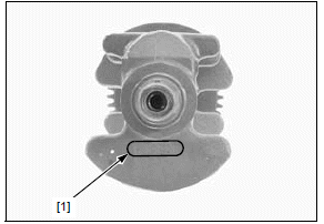
Numbers (1, 2 or 3) on the crank weight are main journal O.D. codes from left to right.
If you are replacing the crankshaft, record the corresponding main journal O.D. code numbers [1] from the crank weight.
If you are reusing the crankshaft, measure the crankpin O.D. with a micrometer.
Cross-reference the main journal and bearing support codes to determine the replacement bearing color code [1].
MAIN JOURNAL BEARING THICKNESS:
- Black
- Brown
- Green
- Yellow
- Pink
MAIN JOURNAL BEARING SELECTION TABLE:
NOTICE
After selecting new bearings, recheck the clearance with a plastigauge. Incorrect clearance can cause severe engine damage.
BEARING INSTALLATION
Clean the bearing outer surfaces and crankcase bearing supports.
Install the main journal bearing inserts [1] onto the crankcase bearing supports, aligning each tab with each groove.
Crankpin bearing
NOTICE
Do not interchange the bearing inserts. They must be installed in their original locations or the correct bearing oil clearance may not be obtained, resulting in engine damage.
BEARING INSPECTION
Remove the crankshaft.
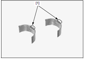
Check the crankpin bearing inserts [1] for unusual wear or peeling.
Check the bearing tabs [2] for damage.
If the crankpin bearing is damaged, select a replacement bearing.
OIL CLEARANCE INSPECTION
Remove the crankshaft.
Clean the mating surface of the connecting rod and crankpin bearing cap with solvent and blow them with compressed air.
Clean off any oil from the bearing inserts and crankpins.
Install the crankshaft onto the upper crankcase.
Set the connecting rods onto the crankpins.
Do not rotate the crankshaft during inspection.
Put a strip of plastigauge [1] lengthwise on each crankpin avoiding the oil hole.
Install the crankpin bearing caps [1] by aligning the I.D.
code number on the connecting rod and bearing cap.
NOTICE
Be sure to install each part in its original position, as noted during removal.
Apply engine oil to the crankpin bearing cap nut [1] threads and seating surfaces.
Install and tighten the crankpin bearing cap nuts in 2 or 3 steps alternately to the specified torque.
TORQUE:35.2 N*m (3.6 kgf*m, 26 lbf*ft)
Remove the bearing caps.
Measure the compressed plastigauge at its widest point on the crankpin to determine the oil clearance.
SERVICE LIMIT: 0.06 mm (0.002 in)
If the oil clearance exceeds the service limit, select the correct replacement bearings.
BEARING SELECTION
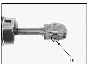
Numbers on the connecting rods are the codes for the connecting rod I.D.
Record the connecting rod I.D. code number [1] or measure the I.D. with the connecting rod bearing cap installed without bearing inserts.
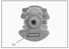
Letters (A, B or C) on the crank weight are the crankpin O.D. codes from left to right.
If you are replacing the crankshaft, record the corresponding crankpin O.D. code letter [1].
If you are reusing the crankshaft, measure the crankpin O.D. with a micrometer.
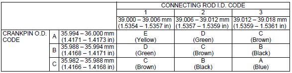
Cross-reference the connecting rod and crankpin codes to determine the replacement bearing color code [1].
CRANKPIN BEARING THICKNESS:
- Blue
- Black
- Brown
- Green
- Yellow
CRANKPIN BEARING SELECTION TABLE:
NOTICE
After selecting new bearings, recheck the clearance with a plastigauge. Incorrect clearance can cause severe engine damage.
BEARING INSTALLATION
Clean the bearing outer surfaces, crankpin bearing cap and connecting rod.
Install the crankpin bearing inserts [1] onto the bearing cap and connecting rod, aligning each tab with each groove.
See also:
 Honda CBR650 - Service manual > Service information
GENERAL The crankcase must be separated to service the crankshaft, cylinder, piston/connecting rod and piston oil jet. Refer to procedures for crankcase separation. Mark and store the connecting rods, bearing caps and bearing inserts to be sure of their correct locations for reassembly. The crankpin and main journal bearing inserts are select fit and are identified by color codes. Select replacement bearings from the code tables. After selecting new bearings, recheck the oil clearance with a plastigauge. Incorrect oil clearance can cause major engine damage.
Honda CBR650 - Service manual > Piston/cylinder
PISTON/CONNECTING ROD REMOVAL NOTICE Before piston removal, place a clean shop towel around the connecting rod to prevent damaging the cylinder sleeve. Do not try to remove the piston/connecting rod assembly from bottom of the cylinder; the assembly will get stuck in the gap between the cylinder liner and the upper crankcase. Do not interchange the bearing inserts. They must be installed in their original locations or the correct bearing oil clearance may not be obtained, resulting in engine damage.
 Rider's Manual BMW R 1250 GS GSA
 Owner's Manual Harley-Davidson Sportster XL1200X Forty-Eight
 Owner's Manual Honda CBR650R
 Service manual Honda CBR650
 Owner's Manual Honda PCX125
 Owner's Manual Kawasaki Z1000SX
 Service manual Kawasaki Z1000SX
 Owner's Manual Lexmoto Echo
 Owner's Manual Royal Enfield Interceptor 650
 Service manual Royal Enfield Interceptor 650
 Owner's Manual Yamaha MT-07