 Honda CBR650 - Service manual > Service information
GENERAL
NOTICE
- The ABS modulator may be damaged if dropped. Also if a connector is disconnected when current is flowing, the excessive voltage may damage the control unit. Always turn off the ignition switch before servicing.
- Spilling brake fluid will severely damage plastic parts and painted surfaces. It is also harmful to some rubber parts.
- This section covers service of the Anti-lock Brake System (ABS). For other service (conventional brake) of the brake system, see Hydraulic Brake section.
- The ABS control unit is integrated in the modulator. Do not disassemble the ABS modulator. Replace the ABS modulator as an assembly when the it is faulty.
- The ABS control unit performs pre-start self-diagnosis to check whether the ABS functions normally until the vehicle speed reaches 10 km/h (6 mph). After pre-start self-diagnosis, the ABS control unit monitors the ABS functions and vehicle running condition constantly until the ignition switch is turned OFF (ordinary self-diagnosis).
- When the ABS control unit detects a problem, it stops the ABS function and switches back to the conventional brake operation, and the ABS indicator blinks or stays on. Take care during the test-ride.
- Read "ABS Troubleshooting Information" carefully, inspect and troubleshoot the ABS system according to the troubleshooting flow chart. Observe each step of the procedures one by one. Write down the DTC and probable faulty part before starting diagnosis and troubleshooting.
- Use a fully charged battery. Do not diagnose with a charger connected to the battery.
- After troubleshooting, erase the DTC and perform the pre-start self-diagnosis to be sure that the ABS indicator is operating normally.
- Troubles not resulting from a faulty ABS (e.g. brake disc squeak, unevenly worn brake pad) cannot be recognized by the ABS diagnosis system.
- When the wheel speed sensor and/or pulser ring is replaced, be sure to check the air gap.
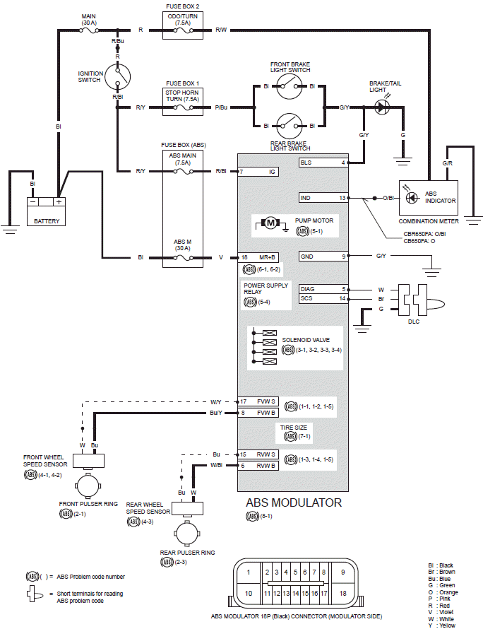
- The following color codes are used throughout this section.
Bl = Black
Br = Brown
Bu = Blue
G = Green
Gr = Gray
Lb = Light Blue
Lg = Light Green
O = Orange
P = Pink
R = Red
V = Violet
W = White
Y = Yellow
System location
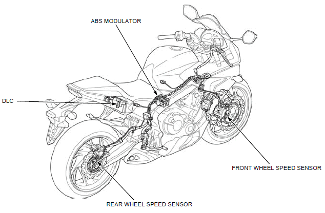
- ABS MODULATOR
- DLC
- REAR WHEEL SPEED SENSOR
- FRONT WHEEL SPEED SENSOR
System diagram
ABS troubleshooting information
SYSTEM DESCRIPTION
SUMMARY OF ABS PRE-START SELF-DIAGNOSIS SYSTEM
The ABS pre-start self-diagnosis system diagnoses the electrical system as well as the operating status of the modulator. When there is any abnormality, the problem and the associated part can be detected by reading the DTC.
When the motorcycle is running, pulse signals generated at the front and rear wheel speed sensors are sent to the ABS control unit.
When the vehicle speed reaches approximately 6 km/h (4 mph), the ABS control unit operates the pump motor to check it. When the vehicle speed reaches 10 km/h (6 mph), the ABS control unit turns off the ABS indicator if the system is normal and the pre-start self-diagnosis is completed.
If any problem is detected, the ABS indicator blinks or comes on and stays on to notify the rider of the problem. The self-diagnosis is also made while the motorcycle is running, and the ABS indicator blinks when a problem is detected.
When the ABS indicator blinks, the cause of the problem can be identified by reading the DTC.
If the ABS indicator does not come on when the ignition switch is turned ON, or the ABS indicator stays on after the pre-start self-diagnosis is completed although the ABS system is normal, the ABS indicator circuit may be faulty. Follow the troubleshooting.
Pre-start serf-diagnosis when the system is normal:
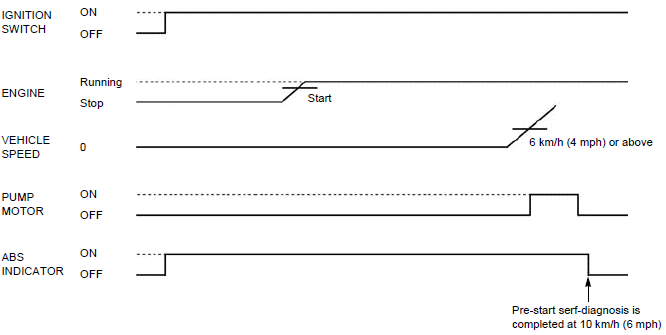
PRE-START SELF-DIAGNOSIS PROCEDURE (Daily check)
1. Turn the ignition switch ON with the engine stop switch " ".
".
2. Make sure the ABS indicator comes on.
3. Start the engine.
4. Ride the motorcycle and increase the vehicle speed to approximately 10 km/h (6 mph).
5. The ABS is normal if the ABS indicator goes off.
MCS INFORMATION
- The MCS can read out and erase the DTC.
How to connect the MCS
Remove the seat.
Turn the ignition switch OFF.
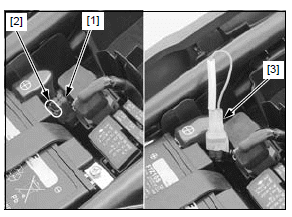
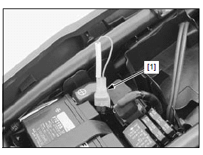
Release the DLC [1] from the stay [2], then remove the dummy connector from the DLC.
Connect the MCS to the DLC.
Turn the ignition switch ON with the engine stop switch ""
and check the DTC.

DTC READOUT
NOTE:
- The DTC is not erased by turning the ignition switch OFF while the DTC is being output. Note that turning the ignition switch ON again does not indicate the DTC. To show the DTC again, repeat the DTC readout procedures from the beginning.
- Be sure to record the indicated DTC(s).
- After diagnostic troubleshooting, erase the DTC and perform the pre-start self-diagnosis procedure to be sure that there is no problem in the ABS.
- Do not apply the brake during DTC readout.
Connect the MCS to the DLC.
Read the DTC and follow the DTC index.
- If the MCS is not available, perform the following.
Reading DTC with the ABS indicator
Remove the seat.
Turn the ignition switch OFF.
Release the DLC [1] from the stay [2], then remove the dummy connector from the DLC.
Short the DLC terminals using the special tool.
TOOL:
[3] SCS connector 070PZ-ZY30100
CONNECTION: Brown - Green
Turn the ignition switch ON with the engine stop switch to "".
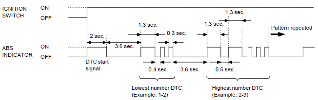
The ABS indicator should come on 2 seconds (start signal) (then goes off 3.6 seconds) and starts DTC indication.
The DTC is indicated by the number of the times of the ABS indicator blinking.
If the DTC is not stored, the ABS indicator stays on.
DTC INDICATION PATTERN
NOTE:
- The ABS indicator indicates the DTC by blinking a specified number of times. The indicator has two types of blinking, a long blink and short blink. The long blink lasts for 1.3 seconds, the short blink lasts for 0.3 seconds. For example, when one long blink is followed by two short blinks, the DTC is 1-2 (one long blink = 1 blink, plus two short blinks = 2 blinks).
- When the ABS control unit stores some DTCs, the ABS indicator shows the DTCs in the order from the lowest number to highest number. For example, when the ABS indicator indicates DTC 1-2, then indicates DTC 2-3, two failures have occurred.
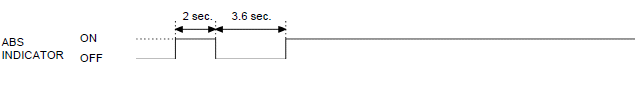
When the DTC is not stored:
ERASING STORED DTC
NOTE:
- The stored DTC can not be erased by simply disconnecting the battery negative cable.
Erase the DTC with the MCS while the engine is stopped.
How to erase the DTC without MCS
1. Connect the SCS connector [1] to the DLC.
2. While squeezing the brake lever, turn the ignition switch ON with the engine
stop switch to "".
The ABS indicator should come on for 2 seconds and go off.
3. Release the brake lever immediately after the ABS indicator goes off.
The ABS indicator should come on.
4. Squeeze the brake lever immediately after the ABS indicator comes on.
The ABS indicator should go off.
5. Release the brake lever immediately after the ABS indicator goes off.
When the DTC is erased, the ABS indicator blinks 2 times and stays on.
If the ABS indicator does not blink 2 times, the self-diagnostic memory has not been erased, so try again.
6. Turn the ignition switch OFF and remove the SCS connector from the DLC.
Install the seat.
CIRCUIT INSPECTION
INSPECTION AT ABS MODULATOR CONNECTOR
Remove the ABS modulator cover.
Turn the ignition switch OFF.
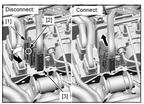
Disconnecting procedure: Turn the lock lever [1] to this side while pressing the lock tab [2] to release it.
Be sure the lock lever is turned all the way and disconnect the ABS modulator 18P (Black) connector [3].
Connecting procedure: Be sure to seat the lock lever against the wire side of the connector fully.
Connect the ABS modulator 18P (Black) connector by pressing it straight at the area as shown (arrow) until the lock tab clicks.
Make sure the connector is locked securely.
- Always clean around and keep any foreign material away from the connector before disconnecting it.
- A faulty ABS is often related to poorly connected or corroded connections. Check those connections before proceeding.
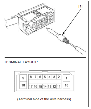
- In testing at ABS modulator 18P (Black) connector terminals (wire harness side; except No. 9 and No. 18 terminals), always use the test probe [1]. Insert the test probe into the connector terminal, then connect the digital multimeter probe to the test probe.
TOOL:
Test probe 07ZAJ-RDJA110
DTC index
NOTE:
- The ABS indicator might blink in the following cases. Correct the faulty
part.
- Incorrect tire pressure.
- Tires not recommended for the motorcycle were installed (incorrect tire size).
- Deformation of the wheel or tire.
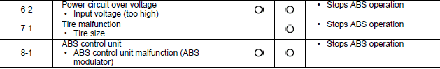
- The ABS indicator might blink while riding under the following
conditions. This is temporary failure. Be sure to erase the DTC. Then, test-ride
the motorcycle above 30 km/h (19 mph) and check the DTC. Ask the rider for
the riding conditions in detail when the motorcycle is brought in for
inspection.
- The motorcycle has continuously run bumpy roads.
- The front wheel leaves the ground for a long time when riding (wheelie).
- Only either the front or rear wheel rotates.
- The ABS operates continuously.
- The ABS control unit has been disrupted by an extremely powerful radio wave (electromagnetic interference).
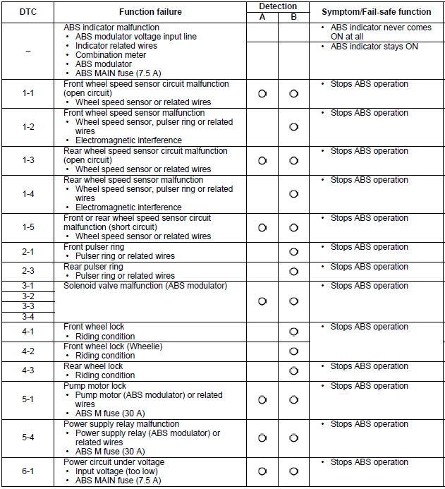
(A) Pre-start self-diagnosis
(B) Ordinary self-diagnosis: diagnoses while the motorcycle is running (after
pre-start self-diagnosis)
ABS indicator circuit troubleshooting
ABS INDICATOR DOES NOT COME ON (when the ignition switch turned ON)
NOTE:
- Before starting this inspection, check the initial operation of the combination meter.
1. Indicator Operation Inspection
Turn the ignition switch OFF.
Disconnect the ABS modulator 18P (Black) connector.
Turn the ignition switch ON with the engine stop switch "".
Check the ABS indicator.
Does the ABS indicator come on?
YES - Faulty ABS modulator
NO - GO TO STEP 2.
2. Indicator Signal Line Short Circuit Inspection
Turn the ignition switch OFF.
Check for continuity between the wire harness side ABS modulator 18P (Black) connector [1] terminal and ground.
TOOL:
Test probe 07ZAJ-RDJA110
Is there continuity? YES - Short circuit in the Orange/black (CBR650FA)/Orange or Orange/black (CB650FA) wire
NO - Faulty combination meter
ABS INDICATOR STAYS ON (Indicator does not go off when the motorcycle is running)
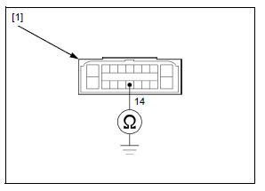
1. Service Check Line Short Circuit Inspection
Turn the ignition switch OFF.
Disconnect the ABS modulator 18P (Black) connector.
Check for continuity between the wire harness side ABS modulator 18P (Black) connector [1] terminal and ground.
TOOL:
Test probe 07ZAJ-RDJA110
CONNECTION: 14 - Ground
Is there continuity?
YES - Short circuit in the Brown wire
NO - GO TO STEP 2.
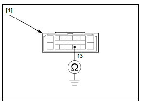
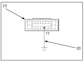
2. Indicator Signal Line Open Circuit Inspection
Short the wire harness side ABS modulator 18P (Black) connector [1] terminal to the ground with a jumper wire [2].
TOOL:
Test probe 07ZAJ-RDJA110
CONNECTION: 13 - Ground
Turn the ignition switch ON with the engine stop switch "".
Check the ABS indicator.
Does it go off?
YES - GO TO STEP 3.
NO -
- Open circuit in the Orange/black (CBR650FA)/Orange or Orange/black (CB650FA) wire
- Faulty combination meter (if the Orange/black or Orange wire is OK)
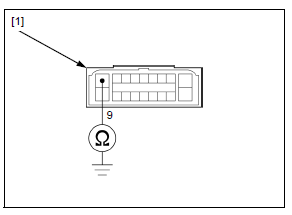
3. Modulator Ground Line Open Circuit Inspection
Turn the ignition switch OFF.
Check for continuity between the wire harness side ABS modulator 18P (Black) connector [1] terminal and ground.
CONNECTION: 9 - Ground
Is there continuity?
YES - GO TO STEP 4.
NO - Open circuit in the Green/yellow wire
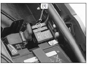
4. Fuse Inspection
Remove the seat.
Open the fuse box cover from the fuse box (ABS).
Check the ABS MAIN fuse (7.5 A) [1] for blown.
Is the fuse blown?
YES - GO TO STEP 5.
NO - GO TO STEP 6.
5. Power Input Line Short Circuit Inspection
With the ABS MAIN fuse (7.5 A) removed, check for continuity between the wire harness side ABS modulator 18P (Black) connector [1] and ground.
TOOL:
Test probe 07ZAJ-RDJA110
CONNECTION: 7 - Ground
Is there continuity?
YES - Short circuit in Red/black wire
NO - Intermittent failure. Replace the ABS MAIN fuse (7.5 A) with a new one, and recheck.

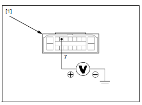
6. Power Input Line Open Circuit Inspection
Install the ABS MAIN fuse (7.5 A).
Turn the ignition switch ON with the engine stop switch "".
Measure the voltage between the wire harness side ABS modulator 18P (Black) connector [1] terminal and ground.
TOOL: Test probe 07ZAJ-RDJA110
CONNECTION: 7 (+) - Ground (-)
Is there battery voltage?
YES - Faulty ABS modulator
NO - Open circuit in Red/black wire
See also:
 Honda CBR650 - Service manual > ABS troubleshooting
NOTE: Perform inspection with the ignition switch OFF, unless otherwise specified. All connector diagrams in the troubleshooting are viewed from the terminal side. Use a fully charged battery. Do not diagnose with a charger connected to the battery. When the ABS modulator assembly is detected to be faulty, recheck the wire harness and connector connections closely before replacing it. After diagnostic troubleshooting, erase the DTC and test-ride the motorcycle to check that the ABS indicator operates normally during pre-start self-diagnosis.
 Rider's Manual BMW R 1250 GS GSA
 Owner's Manual Harley-Davidson Sportster XL1200X Forty-Eight
 Owner's Manual Honda CBR650R
 Service manual Honda CBR650
 Owner's Manual Honda PCX125
 Owner's Manual Kawasaki Z1000SX
 Service manual Kawasaki Z1000SX
 Owner's Manual Lexmoto Echo
 Owner's Manual Royal Enfield Interceptor 650
 Service manual Royal Enfield Interceptor 650
 Owner's Manual Yamaha MT-07