 Honda CBR650 - Service manual > ABS troubleshooting
NOTE:
- Perform inspection with the ignition switch OFF, unless otherwise specified.
- All connector diagrams in the troubleshooting are viewed from the terminal side.
- Use a fully charged battery. Do not diagnose with a charger connected to the battery.
- When the ABS modulator assembly is detected to be faulty, recheck the wire harness and connector connections closely before replacing it.
- After diagnostic troubleshooting, erase the DTC and test-ride the motorcycle to check that the ABS indicator operates normally during pre-start self-diagnosis.
DTC 1-1, 1-2, 2-1, 4-1 or 4-2 (Front Wheel Speed Sensor Circuit/Front Wheel Speed Sensor/Front Pulser Ring/Front Wheel Lock)
NOTE:
- The ABS indicator might blink under unusual riding or conditions. This
is temporary failure.
Erase the DTC then test-ride the motorcycle above 30 km/h (19 mph) and check that the ABS indicator operates normally.
- If the DTC 4-1 is indicated, check the front brake for drag.
1. Speed Sensor Air Gap Inspection
Measure the air gap between the speed sensor and pulser ring.
Is the air gap correct?
YES - GO TO STEP 2.
NO - Check each part for deformation and looseness and correct accordingly.
Recheck the air gap.
2. Speed Sensor Condition Inspection
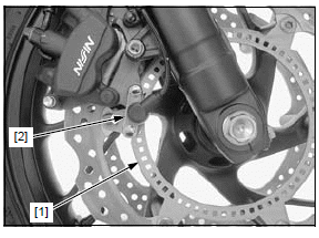
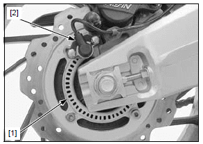
Inspect the area around the front wheel speed sensor: Check that there is iron or other magnetic deposits between the pulser ring [1] and wheel speed sensor [2], and the pulser ring slots for obstructions.
Check the installation condition of the pulser ring or wheel speed sensor for looseness.
Check the pulser ring and sensor tip for deformation or damage (e.g., chipped pulser ring teeth).
Are the sensor and pulser ring in good condition?
YES - GO TO STEP 3.
NO - Remove any deposits. Install properly or replace faulty part.
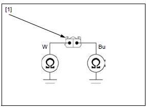
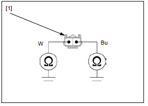
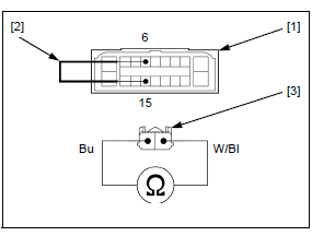
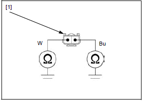
3. Front Wheel Speed Sensor Line Short Circuit Inspection (at sensor side)
Turn the ignition switch OFF.
Disconnect the front wheel speed sensor 2P (Blue) connector.
Check for continuity between each terminal of the sensor side front wheel speed sensor 2P (Blue) connector [1] and ground.
CONNECTION:
White - Ground
Blue - Ground
Is there continuity?
YES - Faulty front wheel speed sensor
NO - GO TO STEP 4.
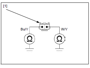
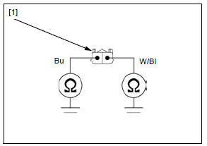
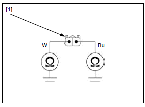
4. Front Wheel Speed Sensor Line Short Circuit Inspection
Disconnect the ABS modulator 18P (Black) connector.
Check for continuity between each terminal of the wire harness side front wheel speed sensor 2P (Blue) connector [1] and ground.
CONNECTION:
Blue/yellow - Ground
White/yellow - Ground
Is there continuity?
YES -
- Short circuit in the Blue/yellow wire
- Short circuit in the White/yellow wire
NO - GO TO STEP 5.
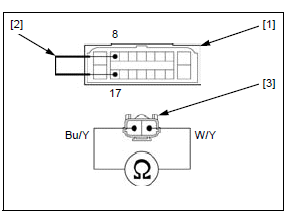
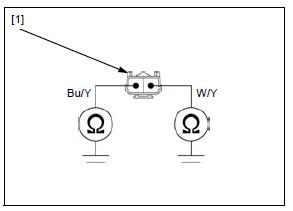
5. Front Wheel Speed Sensor Line Open Circuit Inspection
Short the wire harness side ABS modulator 18P (Black) connector [1] terminals with a jumper wire [2].
CONNECTION: 8 - 17
Check for continuity between the wire harness side front wheel speed sensor 2P (Blue) connector [3] terminals.
CONNECTION: Blue/yellow - White/yellow
Is there continuity?
YES - GO TO STEP 6.
NO - Open circuit in the Blue/yellow or White/ yellow wire
6. Failure Reproduction with a New Speed Sensor
Replace the front wheel speed sensor with a new one.
Connect the ABS modulator 18P (Black) and front wheel speed sensor 2P (Blue) connectors.
Erase the DTC.
Test-ride the motorcycle above 30 km/h (19 mph).
Recheck the DTC.
Is the DTC 1-1, 1-2, 2-1, 4-1 or 4-2 indicated?
YES - Faulty ABS modulator
NO - Faulty original wheel speed sensor
DTC 1-3, 1-4, 2-3, or 4-3 (Rear Wheel Speed Sensor Circuit/Rear Wheel Speed Sensor/Rear Pulser Ring/Rear Wheel Lock)
NOTE:
- The ABS indicator might blink under unusual riding or conditions. This
is temporary failure.
Erase the DTC then test-ride the motorcycle above 30 km/h (19 mph) and check that the ABS indicator operates normally.
- If the DTC 4-3 is indicated, check the rear brake for drag.
1. Speed Sensor Air Gap Inspection
Measure the air gap between the speed sensor and pulser ring.
Is the air gap correct?
YES - GO TO STEP 2.
NO - Check each part for deformation and looseness and correct accordingly.
Recheck the air gap.
2. Speed Sensor Condition Inspection
Inspect the area around the rear wheel speed sensor: Check that there is iron or other magnetic deposits between the pulser ring [1] and wheel speed sensor [2], and the pulser ring slots for obstructions.
Check the installation condition of the pulser ring or wheel speed sensor for looseness.
Check the pulser ring and sensor tip for deformation or damage (e.g., chipped pulser ring teeth).
Are the sensor and pulser ring in good condition?
YES - GO TO STEP 3.
NO - Remove any deposits. Install properly or replace faulty part.
3. Rear Wheel Speed Sensor Line Short Circuit Inspection (at sensor side)
Turn the ignition switch OFF.
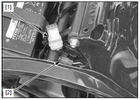
Remove the seat.
Release the optional 6P connector [1] from the stay.
Release the rear wheel speed sensor 2P (Gray) connector [2] from the stay and disconnect it.
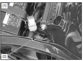
Check for continuity between each terminal of the sensor side rear wheel speed sensor 2P (Gray) connector [1] and ground.
CONNECTION:
Blue - Ground
White - Ground
Is there continuity?
YES - Faulty rear wheel speed sensor
NO - GO TO STEP 4.
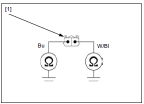
4. Rear Wheel Speed Sensor Line Short Circuit Inspection
Disconnect the ABS modulator 18P (Black) connector.
Check for continuity between each terminal of the wire harness side rear wheel speed sensor 2P (Gray) connector [1] and ground.
CONNECTION:
White/black - Ground
Blue - Ground
Is there continuity?
YES -
- Short circuit in the White/black wire
- Short circuit in the Blue wire
NO - GO TO STEP 5.
5. Rear Wheel Speed Sensor Line Open Circuit Inspection
Short the wire harness side ABS modulator 18P (Black) connector [1] terminals with a jumper wire [2].
CONNECTION: 6 - 15
Check for continuity between the wire harness side rear wheel speed sensor 2P (Gray) connector [3] terminals.
CONNECTION: White/black - Blue
Is there continuity?
YES - GO TO STEP 6.
NO - Open circuit in the White/black or Blue wire
6. Failure Reproduction with a New Speed Sensor
Replace the rear wheel speed sensor with a new one.
Connect the ABS modulator 18P (Black) and rear wheel speed sensor 2P (Gray) connectors.
Erase the DTC.
Test-ride the motorcycle above 30 km/h (19 mph).
Recheck the DTC.
Is the DTC 1-3, 1-4, 2-3, or 4-3 indicated?
YES - Faulty ABS modulator
NO - Faulty original wheel speed sensor
DTC 1-5 (Front or Rear Wheel Speed Sensor Circuit; Short)
1. Front Wheel Speed Sensor Line Short Circuit Inspection (at sensor side)
Turn the ignition switch OFF.
Disconnect the front wheel speed sensor 2P (Blue) connector.
Check for continuity between each terminal of the sensor side front wheel speed sensor 2P (Blue) connector [1] and ground.
CONNECTION:
White - Ground
Blue - Ground
Is there continuity?
YES - Faulty front wheel speed sensor
NO - GO TO STEP 2.
2. Front Wheel Speed Sensor Line Short Circuit Inspection
Disconnect the ABS modulator 18P (Black) connector.
Check for continuity between each terminal of the wire harness side front wheel speed sensor 2P (Blue) connector [1] and ground.
CONNECTION:
Blue/yellow - Ground
White/yellow - Ground
Is there continuity?
YES -
- Short circuit in the Blue/yellow wire
- Short circuit in the White/yellow wire
NO - GO TO STEP 3.
3. Rear Wheel Speed Sensor Line Short Circuit Inspection (at sensor side)
Turn the ignition switch OFF.
Remove the seat.
Release the optional 6P connector [1] from the stay.
Release the rear wheel speed sensor 2P (Gray) connector [2] from the stay and disconnect it.
Check for continuity between each terminal of the sensor side rear wheel speed sensor 2P (Gray) connector [1] and ground.
CONNECTION:
Blue - Ground
White - Ground
Is there continuity?
YES - Faulty rear wheel speed sensor
NO - GO TO STEP 4.
4. Rear Wheel Speed Sensor Line Short Circuit Inspection
Check for continuity between each terminal of the wire harness side rear wheel speed sensor 2P (Gray) connector [1] and ground.
CONNECTION: White/black - Ground Blue - Ground
Is there continuity?
YES -
- Short circuit in the White/black wire
- Short circuit in the Blue wire
NO - Faulty ABS modulator
DTC 3-1, 3-2, 3-3 or 3-4 (Solenoid Valve)
1. Failure Reproduction
Erase the DTC.
Test-ride the motorcycle above 30 km/h (19 mph).
Recheck the DTC.
Is the DTC 3-1, 3-2, 3-3 or 3-4 indicated?
YES - Faulty ABS modulator
NO - Solenoid valve is normal (intermittent failure).
DTC 5-1 or 5-4 (Pump Motor Lock/ Power Supply Relay)
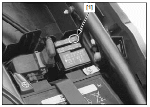
1. Fuse Inspection
Turn the ignition switch OFF.
Remove the seat.
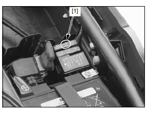
Remove the fuse box cover from the fuse box (ABS).
Check the ABS M fuse (30 A) [1] for blown.
Is the fuse blown?
YES - GO TO STEP 2.
NO - GO TO STEP 3.
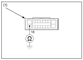
2. Motor Power Input Line Short Circuit Inspection
Disconnect the ABS modulator 18P (Black) connector.
With the ABS M fuse (30 A) removed, check for continuity between the wire harness side ABS modulator 18P (Black) connector [1] terminal and ground.
CONNECTION: 18 - Ground
Is there continuity?
YES - Short circuit in the Violet wire between the fuse box (ABS) and ABS modulator 18P (Black) connector
NO - Intermittent failure. Replace the ABS M fuse (30 A) with a new one, and recheck.
3. Motor Power Input Line Open Circuit Inspection
Install the ABS M fuse (30 A).
Disconnect the ABS modulator 18P (Black) connector.
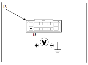
Measure the voltage between the wire harness side ABS modulator 18P (Black) connector [1] terminal and ground.
CONNECTION: 18 (+) - Ground (-)
Is there battery voltage?
YES - GO TO STEP 4.
NO - Open circuit in the Violet or Black wire between the battery and ABS modulator 18P (Black) connector
4. Failure Reproduction
Turn the ignition switch OFF.
Connect the ABS modulator 18P (Black) connector.
Erase the DTC.
Test-ride the motorcycle above 30 km/h (19 mph).
Recheck the DTC.
Is the DTC 5-1 or 5-4 indicated?
YES - Faulty ABS modulator
NO - Pump motor is normal (intermittent failure).
DTC 6-1 or 6-2 (Power Circuit)
1. Fuse Inspection
Turn the ignition switch OFF.
Remove the seat.
Remove the fuse box cover from the fuse box (ABS).
Check the ABS MAIN fuse (7.5 A) [1] for blown.
Is the fuse blown?
YES - GO TO STEP 2.
NO - GO TO STEP 3.
2. Power Input Line Short Circuit Inspection
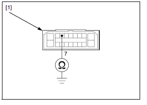
Disconnect the ABS modulator 18P (Black) connector.
With the ABS MAIN fuse (7.5 A) removed, check for continuity between the wire harness side ABS modulator 18P (Black) connector [1] and ground.
TOOL:
Test probe 07ZAJ-RDJA110
CONNECTION: 7 - Ground
Is there continuity?
YES - Short circuit in Red/black wire
NO - Intermittent failure. Replace the ABS MAIN fuse (7.5 A) with a new one, and recheck.
3. Power Input Line Open Circuit Inspection
Install the ABS MAIN fuse (7.5 A).
Turn the ignition switch ON with the engine stop switch " ".
".
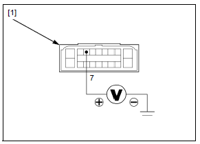
Measure the voltage between the wire harness side ABS modulator 18P (Black) connector [1] terminal and ground.
TOOL: Test probe 07ZAJ-RDJA110
CONNECTION: 7 (+) - Ground (-)
Is there battery voltage?
YES - GO TO STEP 4.
NO - Open circuit in Red/black or Red/yellow wire
4. Failure Reproduction
Turn the ignition switch OFF.
Connect the ABS modulator 18P (Black) connector.
Erase the DTC.
Test-ride the motorcycle above 30 km/h (19 mph).
Recheck the DTC.
Is the DTC 6-1 or 6-2 indicated?
YES - Faulty ABS modulator
NO - Power circuit is normal (intermittent failure)
DTC 7-1 (Tire Size)
NOTE:
- Check the following and correct the faulty part.
- Incorrect tire pressure.
- Tires not recommended for the motorcycle were installed (incorrect tire size).
- Deformation of the wheel or tire.
1. Failure Reproduction
If the above items are normal, recheck the DTC indication: Erase the DTC.
Test-ride the motorcycle above 30 km/h (19 mph).
Recheck the DTC.
Is the DTC 7-1 indicated?
YES - Faulty ABS modulator
NO - Tire size is normal (intermittent failure)
DTC 8-1 (ABS Control Unit)
1. Failure Reproduction
Erase the DTC.
Test-ride the motorcycle above 30 km/h (19 mph).
Recheck the DTC.
Is the DTC 8-1 indicated?
YES - Faulty ABS modulator
NO - ABS control unit is normal (intermittent failure)
See also:
 Honda CBR650 - Service manual > Service information
GENERAL NOTICE The ABS modulator may be damaged if dropped. Also if a connector is disconnected when current is flowing, the excessive voltage may damage the control unit. Always turn off the ignition switch before servicing. Spilling brake fluid will severely damage plastic parts and painted surfaces. It is also harmful to some rubber parts.
Honda CBR650 - Service manual > Wheel speed sensor
AIR GAP INSPECTION Support the motorcycle securely using a hoist or equivalent and raise the wheel off the ground. Measure the clearance (air gap) between the sensor and pulser ring at several points by turning the wheel slowly.
 Rider's Manual BMW R 1250 GS GSA
 Owner's Manual Harley-Davidson Sportster XL1200X Forty-Eight
 Owner's Manual Honda CBR650R
 Service manual Honda CBR650
 Owner's Manual Honda PCX125
 Owner's Manual Kawasaki Z1000SX
 Service manual Kawasaki Z1000SX
 Owner's Manual Lexmoto Echo
 Owner's Manual Royal Enfield Interceptor 650
 Service manual Royal Enfield Interceptor 650
 Owner's Manual Yamaha MT-07