 Honda CBR650 - Service manual > Wheel speed sensor
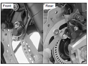
AIR GAP INSPECTION
Support the motorcycle securely using a hoist or equivalent and raise the wheel off the ground.
Measure the clearance (air gap) between the sensor and pulser ring at several points by turning the wheel slowly.
It must be within specification.
STANDARD: 0.4 - 1.2 mm (0.02 - 0.05 in)
The clearance (air gap) cannot be adjusted.
If it is not within specification, check each part for deformation, looseness or damage.
Check the wheel speed sensor for damage, and replace if necessary.
Check the pulser ring for deformation or damage, and replace if necessary.
- Front pulser ring
- Rear pulser ring
REMOVAL/INSTALLATION
FRONT WHEEL SPEED SENSOR
Lift the fuel tank and support it.
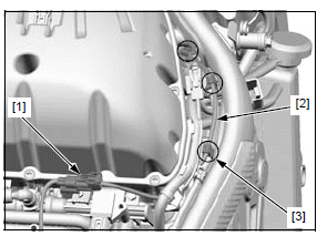
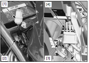
Disconnect the front wheel speed sensor 2P (Blue) connector [1].
Release the front wheel speed sensor wire [2] from the clamps [3].
Remove the two wire clips [1].
Release the front wheel speed sensor wire [2] from the clamps [3].
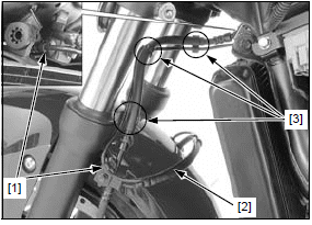
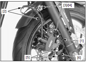
Release the front wheel speed sensor wire [1] from the clamps [2].
Remove the bolts [3] and front wheel speed sensor wire guides [4].
Remove the two bolts [5] and front wheel speed sensor [6].
Installation is in the reverse order of removal.
NOTE:
- Clean the sensor tip and sensor installation area (caliper bracket) thoroughly, and be sure that no foreign materials are allowed.
After installation, check the air gap.
REAR WHEEL SPEED SENSOR
Lift the fuel tank and support it.
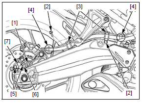
Release the optional 6P connector [1] from the stay and disconnect the rear wheel speed sensor 2P (Gray) connector [2].
Remove the wire clip [3] of the rear wheel speed sensor wire [4].
Remove the following:
- Wire clip [1]
- Two bolts [2] and clamps [3]
- Two wire clips [4]
- Two bolts [5]
- Wire stay [6]
- Rear wheel speed sensor [7]
Installation is in the reverse order of removal.
NOTE:
- Clean the sensor tip and sensor installation area (caliper bracket) thoroughly, and be sure that no foreign materials are allowed.
After installation, check the air gap.
ABS modulator
REMOVAL/INSTALLATION
Drain the brake fluid from the rear brake hydraulic systems.
Remove the following:
- Throttle body
- ABS modulator cover
Disconnect the ABS modulator 18P (Black) connector.
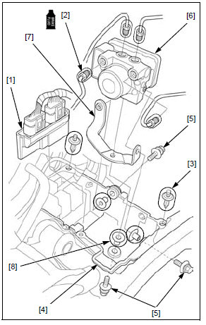
Pull the ECM [1] upward as shown.
Loosen the brake pipe joint nuts [2] to disconnect the brake pipes.
- When disconnecting, cover the end of the brake pipes to prevent contamination.
Remove the trim clips [3] and slightly pull the ABS modulator tray [4] upward.
Remove the following:
- Three washer bolts [5]
- ABS modulator [6] and stay [7]
- Three collars [8]
Installation is in the reverse order of removal.
- Apply brake fluid to the threads of the brake pipe joint nuts.
TORQUE:
Brake pipe joint nut: 14 N*m (1.4 kgf*m, 10 lbf*ft)
Fill and bleed the front and rear brake hydraulic systems.
See also:
 Honda CBR650 - Service manual > ABS troubleshooting
NOTE: Perform inspection with the ignition switch OFF, unless otherwise specified. All connector diagrams in the troubleshooting are viewed from the terminal side. Use a fully charged battery. Do not diagnose with a charger connected to the battery. When the ABS modulator assembly is detected to be faulty, recheck the wire harness and connector connections closely before replacing it. After diagnostic troubleshooting, erase the DTC and test-ride the motorcycle to check that the ABS indicator operates normally during pre-start self-diagnosis.
 Rider's Manual BMW R 1250 GS GSA
 Owner's Manual Harley-Davidson Sportster XL1200X Forty-Eight
 Owner's Manual Honda CBR650R
 Service manual Honda CBR650
 Owner's Manual Honda PCX125
 Owner's Manual Kawasaki Z1000SX
 Service manual Kawasaki Z1000SX
 Owner's Manual Lexmoto Echo
 Owner's Manual Royal Enfield Interceptor 650
 Service manual Royal Enfield Interceptor 650
 Owner's Manual Yamaha MT-07