 Kawasaki Z1000SX - Service manual > Shift Drum and Fork Removal
- Remove:
Lower Crankcase Half (see Crankcase Splitting)
Transmission Shafts (see Transmission Shaft Removal)
Gear Positioning Lever (see External Shift Mechanism Removal)
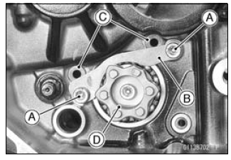
Bolts [A]
Shift Drum Bearing Holder [B] - Pull out the shift rods [C], and take off the shift forks.
- Pull out the shift drum [D].
Shift Drum and Fork Installation
- Apply engine oil to the shift drum, forks and rods.
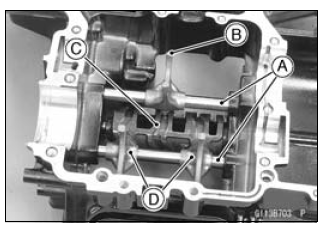
- Install the shift rods [A], noting the groove position.
- The rods are identical.
- Position the one with shortest ears [B] on the drive shaft and place the pin in the center groove in the shift drum [C].
- The two forks [D] on the output shaft are identical. -Install the forks so that its "0061" and "0062" side faces engine left side.
- Apply a non-permanent locking agent to the threads of the shift drum
bearing holder bolts, and tighten them.
Torque - Shift Drum Bearing Holder Bolts: 12 N*m (1.2 kgf*m, 106 in*lb)
Shift Drum Disassembly
- Remove the shift drum (see Shift Drum and Fork Removal).
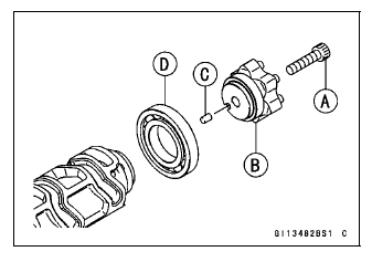
- While holding the shift drum with a vise, remove the shift drum cam bolt [A].
- Remove:
Shift Drum Cam [B]
Dowel Pin [C]
Bearing [D]
Shift Drum Assembly
- Be sure to install the dowel pin.
- Apply a non-permanent locking agent to the threads of the shift drum
bearing holder bolt, and tighten it.
Torque - Shift Drum Cam Bolt: 12 N*m (1.2 kgf*m, 106 in*lb)
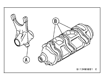
Shift Fork Bending Inspection
- Visually inspect the shift forks, and replace any fork that is bent. A
bent fork could cause difficulty in shifting, or allow the transmission to
jump out of gear when under power.
90º [A]

Shift Fork/Gear Groove Wear Inspection
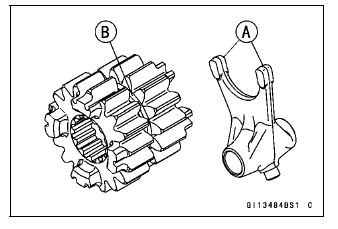
- Measure the thickness of the shift fork ears [A], and measure the width
of the gear grooves [B].
If the thickness of a shift fork ear is less than the service limit, the shift fork must be replaced.
Shift Fork Ear Thickness
Standard: 5.9 - 6.0 mm (0.232 - 0.236 in.)
Service Limit: 5.8 mm (0.228 in.)
If the gear groove is worn over the service limit, the gear must be replaced.
Gear Groove Width
Standard: 6.05 - 6.15 mm (0.238 - 0.242 in.)
Service Limit: 6.25 mm (0.246 in.)
Shift Fork Guide Pin/Drum Groove Wear Inspection
- Measure the diameter of each shift fork guide pin [A], and measure the
width of each shift drum groove [B].
If the guide pin on any shift fork is less than the service limit, the fork must be replaced.
Shift Fork Guide Pin Diameter
Standard: 6.9 - 7.0 mm (0.272 - 0.276 in.)
Service Limit: 6.8 mm (0.268 in.)
If any shift drum groove is worn over the service limit, the drum must be replaced.
Shift Drum Groove Width
Standard: 7.05 - 7.20 mm (0.278 - 0.283 in.)
Service Limit: 7.3 mm (0.287 in.)
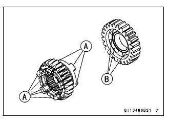
Gear Dog and Gear Dog Hole Damage Inspection
- Visually inspect the gear dogs [A] and gear dog holes [B].
Replace any damaged gears or gears with excessively worn dogs or dog holes.
Ball Bearing, Needle Bearing, and Oil Seal
Ball and Needle Bearing Replacement
NOTICE Do not remove the ball or needle bearings unless it is necessary. Removal may damage them.
- Using a press or puller, remove the ball bearing and/or needle bearings.
NOTE
- In the absence of the above mentioned tools, satisfactory results may be obtained by heating the case to approximately 93ºC (200ºF) max., and tapping the bearing in or out.
NOTICE Do not heat the case with a torch. This will warp the case. Soak the case in oil and heat the oil.
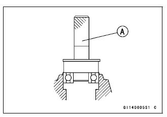
- Using a press and the bearing driver set [A], install the new ball
bearing until it stops at the bottom of its housing.
- The new needle bearings must be pressed into the crankcase so that the end is flush with the end of the hole.
Special Tool - Bearing Driver Set: 57001-1129
Ball and Needle Bearing Wear
NOTICE Do not remove the bearings for inspection. Removal may damage them.
- Check the ball bearings.
- Since the ball bearings are made to extremely close tolerances, the
wear must be judged by feel rather than measurement.
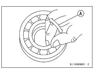
Clean each bearing in a high-flash point solvent, dry it (do not spin the bearing while it is dry), and oil it with engine oil.
- Spin [A] the bearing by hand to check its condition.
If the bearing is noisy, does not spin smoothly, or has any rough spots, replace it.
- Since the ball bearings are made to extremely close tolerances, the
wear must be judged by feel rather than measurement.
- Check the needle bearings.
- The rollers in a needle bearing normally wear very little, and wear is difficult to measure. Instead of measuring, inspect the bearing for abrasion, color change, or other damage.
If there is any doubt as to the condition of a needle bearing, replace it.
Oil Seal Inspection
- Inspect the oil seals.
Replace it if the lips are misshapen, discolored (indicating that the rubber has deteriorated), hardened or otherwise damaged.
See also:
 Kawasaki Z1000SX - Service manual > Transmission Shaft Assembly
Install the new ball bearing [A] and collar [B] (output shaft) on the each shaft, using the bearing driver. Spacial Tool - Bearing Driver, 32: 57001-382 Apply engine oil to the bushings, ball bearings and shafts. Install the gear bushings [A] on the shaft with their holes [B] aligned. Replace any circlips removed with new ones. Install the circlips [A] so that the opening [B] is aligned with a spline groove [C]. The drive shaft gears can be recognized by size: the gear with the smallest diameter is 1st gear, and the largest one is 6th gear. Be sure that all parts are put back in the correct sequence and all circlips and washers are properly in place. Install the 3rd/4th gear onto the drive shaft with their oil holes aligned. Install the 6th gear bushing onto the drive shaft with their oil holes aligned. The output shaft gears can be recognized by size: the gear with the largest diameter is 1st gear, and the smallest one is 6th gear. Be sure that all parts are put back in the correct sequence and all circlips and washers are properly in place. Install the 6th gear onto the output shaft with their oil holes aligned. Install the 3rd/4th gear bushings onto the output shaft with their oil holes aligned.
 Rider's Manual BMW R 1250 GS GSA
 Owner's Manual Harley-Davidson Sportster XL1200X Forty-Eight
 Owner's Manual Honda CBR650R
 Service manual Honda CBR650
 Owner's Manual Honda PCX125
 Owner's Manual Kawasaki Z1000SX
 Service manual Kawasaki Z1000SX
 Owner's Manual Lexmoto Echo
 Owner's Manual Royal Enfield Interceptor 650
 Service manual Royal Enfield Interceptor 650
 Owner's Manual Yamaha MT-07