 Kawasaki Z1000SX - Service manual > Subthrottle Sensor (Service Code 32)
The subthrottle sensor is a rotating variable resistor that change output voltage according to throttle operating. The ECU senses this voltage change and determines fuel injection quantity, and ignition timing according to engine rpm, and throttle opening.
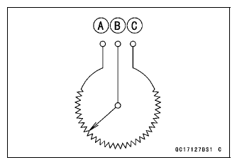
Input Terminal [A]
Output Terminal [B]
Ground Terminal [C]
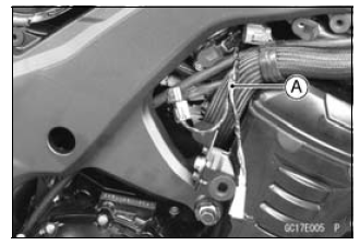
Subthrottle Sensor Removal/Adjustment
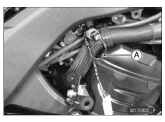
NOTICE Do not remove or adjust the subthrottle sensor [A] since it has been adjusted and set with precision at the factory.
Never drop the throttle body assy especially on a hard surface. Such a shock to the subthrottle sensor can damage it.
Subthrottle Sensor Input Voltage Inspection
NOTE
- Be sure the battery is fully charged.
- Turn the ignition switch OFF.
- Remove the right lower fairing (see Lower Fairing Removal in the Frame chapter).
- Disconnect the subthrottle sensor and connect the harness adapter [A] between these connectors.
Special Tool - Throttle Sensor Setting Adapter: 57001 -1538
- Connect a digital meter to the harness adapter leads.
Subthrottle Sensor Input Voltage
Connections to Adapter:
Digital Meter (+) → W (sensor BL) lead
Digital Meter (-) → BK (sensor BR/BK) lead
- Measure the input voltage with the engine stopped and with the connector joined.
- Turn the ignition switch ON.
Input Voltage
Standard: DC 4.75 - 5.25 V
- Turn the ignition switch OFF.
If the reading is within the standard, check the output voltage (see Subthrottle Sensor Output Voltage Inspection).
If the reading is out of the standard, remove the ECU and check the wiring for continuity between main harness connectors.
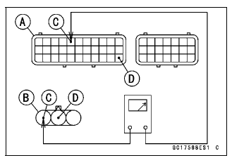
- Disconnect the ECU and sensor connectors.
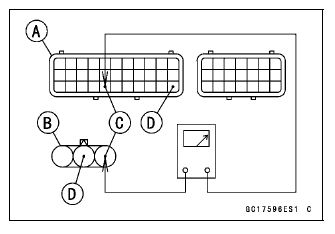
Wiring Inspection
ECU Connector [A] ←→
Subthrottle Sensor Connector [B]
BL lead (ECU terminal 5) [C]
BR/BK lead (ECU terminal 33) [D]
If the wiring is good, check the ECU for its ground and power supply (see ECU Power Supply Inspection).
If the ground and power supply are good, replace the ECU (see ECU Removal/Installation).
Subthrottle Sensor Output Voltage Inspection
- Measure the output voltage at the subthrottle sensor in the same way as
input voltage inspection, note the following.
- Disconnect the subthrottle sensor connector and connect the harness adapter [A] between these connectors.
Special Tool - Throttle Sensor Setting Adapter: 57001 -1538
Subthrottle Sensor Output Voltage
Connections to Adapter:
Digital Meter (+) → R (sensor BR) lead
Digital Meter (-) → BK (sensor BR/BK) lead
- Remove the air cleaner housing (see Air Cleaner Housing Removal).
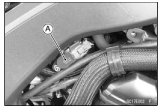
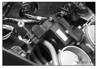
- Disconnect the subthrottle valve actuator harness connector [A].
- Measure the output voltage with the engine stopped with the connector joined.
- Remove the left lower side fairing (see Left Lower Side Fairing Removal in the Frame chapter).
- Turn the ignition switch ON.
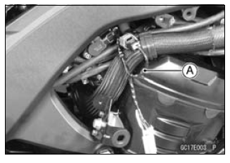
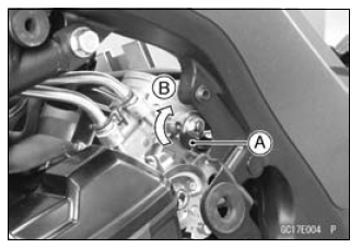
- Measure the output voltage when the subthrottle valve is completely closed by turning the lever [A] fully clockwise [B].
Output Voltage
Standard:
DC 1.08 - 1.12 V at subthrottle valve full close position
DC 4.2 - 4.4 V at subthrottle valve full open position (for
reference)
NOTE
- Turn the lever counterclockwise, confirm the output voltage will be raise.
- The standard voltage refers to the value when the voltage reading at the Input Voltage Inspection shows 5 V exactly.
- When the input voltage reading shows other than 5 V, derive a
voltage range as follows.
Example:
In the case of a input voltage of 4.75 V.
1.08 × 4.75 ÷ 5.00 = 1.03 V
1.12 × 4.75 ÷ 5.00 = 1.06 V
Thus, the valid range is 1.03 - 1.06 V
- Turn the ignition switch OFF.
If the reading is out of the standard, check the subthrottle sensor resistance (see Subthrottle Sensor Resistance Inspection).
If the reading is within the standard, remove the ECU and check the wiring for continuity between main harness connectors.
- Disconnect the ECU and sensor connectors.
Wiring Inspection
ECU Connector [A] ←→
Subthrottle Sensor Connector [B]
BR lead (ECU terminal 27) [C]
BR/BK lead (ECU terminal 33) [D]
If the wiring is good, check the ECU for its ground and power supply (see ECU Power Supply Inspection).
If the ground and power supply are good, replace the ECU (see ECU Removal/Installation).
Subthrottle Sensor Resistance Inspection
- Turn the ignition switch OFF.
- Disconnect the subthrottle sensor connector.
- Disconnect the subthrottle sensor connector and connect the harness adapter [A] to the sensor connector only.
Special Tool - Throttle Sensor Setting Adapter: 57001 -1538
Subthrottle Sensor Output Resistance
Connections to Adapter:
Digital Meter (+) → W (sensor BL) lead
Digital Meter (-) → BK (sensor BR/BK) lead
Standard: 4 - 6 kΩ
If the reading is out of the standard, replace the throttle body assy.
If the reading is within the standard, but the problem still exists, replace the ECU (see ECU Removal/Installation).
Subthrottle Sensor Circuit
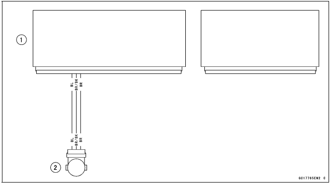
- ECU
- Subthrottle Sensor
See also:
 Kawasaki Z1000SX - Service manual > Vehicle-down Sensor (Service Code 31)
This sensor has a weight [A] with two magnets inside, and sends a signal to the ECU. But when the motorcycle banks 60 - 70º or more to either side (in fact falls down), the weight turns and the signal changes. The ECU senses this change, and stops the fuel pump relay, the fuel injectors and the ignition system.
Kawasaki Z1000SX - Service manual > Oxygen Sensor - not activated (Service Code 33, Equipped Models)
Oxygen Sensor Removal/Installation Refer to the Oxygen Sensor Removal/Installation in the Electrical System chapter. Oxygen Sensor Inspection Warm up the engine thoroughly until the radiator fan starts. Turn the ignition switch OFF. Remove the right fairing (see Lower Fairing Removal in the Frame chapter). Open the clamp [A], and pull out the oxygen sensor lead connector [B]. Disconnect the oxygen sensor lead connector (4 pins connector) and connect the harness adapter [A] between these connectors.
 Rider's Manual BMW R 1250 GS GSA
 Owner's Manual Harley-Davidson Sportster XL1200X Forty-Eight
 Owner's Manual Honda CBR650R
 Service manual Honda CBR650
 Owner's Manual Honda PCX125
 Owner's Manual Kawasaki Z1000SX
 Service manual Kawasaki Z1000SX
 Owner's Manual Lexmoto Echo
 Owner's Manual Royal Enfield Interceptor 650
 Service manual Royal Enfield Interceptor 650
 Owner's Manual Yamaha MT-07