 Kawasaki Z1000SX - Service manual > Vehicle-down Sensor (Service Code 31)
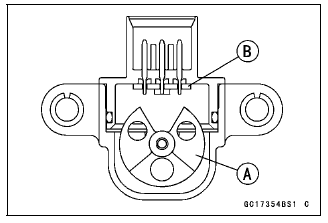
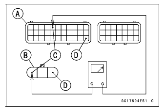
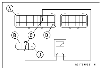
This sensor has a weight [A] with two magnets inside, and sends a signal to the ECU. But when the motorcycle banks 60 - 70º or more to either side (in fact falls down), the weight turns and the signal changes. The ECU senses this change, and stops the fuel pump relay, the fuel injectors and the ignition system.
Hall IC [B]
When the motorcycle is down, the ignition switch is left ON. If the starter button is pushed, the electric starter turns but the engine does not start. To start the engine again, raise the motorcycle, turn the ignition switch OFF, and then ON.
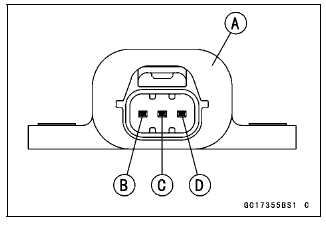
Vehicle-down Sensor [A]
Ground Terminal BR/BK [B]
Output Terminal Y/G [C]
Power Source Terminal BL [D]
Vehicle-down Sensor Removal
NOTICE Never drop the vehicle-down sensor especially on a hard surface. Such a shock to the sensor can damage it.
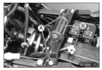
- Remove:
Front Seat (see Front Seat Removal in the Frame chapter)
Fuel Tank (See Fuel Tank Removal)
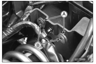
Bolts [A]
Fuel Tank Bracket [B]
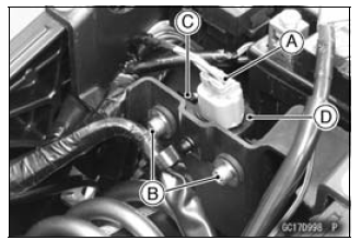
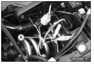
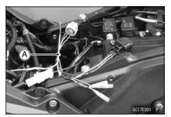
- Remove:
Connector [A]
Bolts [B] and Bracket [C]
Vehicle-down Sensor [D]
Vehicle-down Sensor Installation
- Be sure to install the rubber dampers [A] and collars [B] on the battery case.
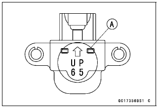
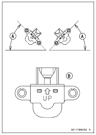
- The UP mark [A] of the sensor should face upward.
WARNING Incorrect installation of the vehicle-down sensor could cause sudden loss of engine power. The rider could lose balance during certain riding situations for an accident resulting in injury or death.
Ensure that the vehicle-down sensor is held in place by the battery case.
Vehicle-down Sensor Input Voltage Inspection
NOTE
- Be sure the battery is fully charged.
- Turn the ignition switch OFF.
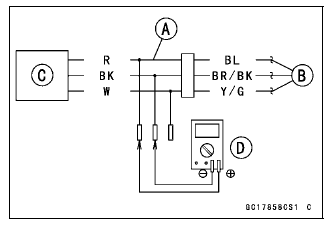
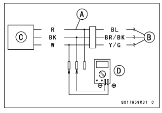
- Disconnect the vehicle-down sensor connector and connect the harness
adapter [A] between these connectors as shown.
Main Harness [B]
Vehicle-down Sensor [C]
Special Tool - Measuring Adapter: 57001-1700
- Connect a digital meter [D] to the harness adapter leads.
Vehicle-down Sensor Input Voltage
Connections to Adapter:
Digital Meter (+) → R (sensor BL) lead
Digital Meter (-) → BK (sensor BR/BK) lead
- Measure the input voltage with the engine stopped and with the connector joined.
- Turn the ignition switch ON.
Input Voltage
Standard: DC 4.75 - 5.25 V
- Turn the ignition switch OFF.
If the reading is within the standard, check the output voltage (see Vehicle-down Sensor Output Voltage Inspection).
If the reading is out of the standard, remove the ECU and check the wiring for continuity between main harness connectors.
- Disconnect the ECU and sensor connections.
Wiring Inspection
ECU Connector [A] ←→
Vehicle-down Sensor Connector [B]
BL lead (ECU terminal 5) [C]
BR/BK lead (ECU terminal 33) [D]
If the wiring is good, check the ECU for its ground and power supply (see ECU Power Supply Inspection).
If the ground and power supply are good, replace the ECU (see ECU Removal/Installation).
Vehicle-down Sensor Output Voltage Inspection
- Remove the vehicle-down sensor (see Vehicle-down Sensor Removal).
- Connect the harness adapter [A] to the vehicle-down sensor connectors as
shown.
Special Tool - Measuring Adapter: 57001-1700
Main Harness [B]
Vehicle-down Sensor [C] - Connect a digital meter [D] to the harness adapter leads.
Vehicle-down Sensor Output Voltage
Connections to Adapter:
Digital Meter (+) → W (sensor Y/G) lead
Digital Meter (-) → BK (sensor BR/BK) lead
- Hold the sensor vertically.
- Measure the output voltage with the engine stopped and with the connector joined.
- Turn the ignition switch ON.
- Tilt the sensor 60 - 70º or more [A] right or left, then hold the sensor almost vertical with the arrow mark pointed up [B], and measure the output voltage.
Output Voltage
Standard:
With sensor tilted 60 - 70º or more right or left: DC 0.65 - 1.35 V
With sensor arrow mark pointed up: DC 3.55 - 4.45 V
NOTE
- If you need to test again, turn the ignition switch OFF, and then ON.
- Turn the ignition switch OFF.
If the reading is out of the standard, replace the sensor.
If the reading is within the standard, remove the ECU and check the wiring for continuity between main harness connectors.
- Disconnect the ECU and sensor connectors.
Wiring Inspection
ECU Connector [A] ←→
Vehicle-down Sensor Connector [B]
Y/G lead (ECU terminal 19) [C]
BR/BK lead (ECU terminal 33) [D]
If the wiring is good, check the ECU for its ground and power supply (see ECU Power Supply Inspection).
If the ground and power supply are good, replace the ECU (see ECU Removal/Installation).
Vehicle-down Sensor Circuit
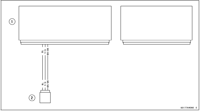
- ECU
- Vehicle-down Sensor
See also:
 Kawasaki Z1000SX - Service manual > Speed Sensor (Service Code 24, 25)
Speed Sensor Removal/Installation Refer to the Speed Sensor Removal/Installation in the Electrical System chapter. Speed Sensor Inspection Refer to the Speed Sensor Inspection in the Electrical System chapter.
Kawasaki Z1000SX - Service manual > Subthrottle Sensor (Service Code 32)
The subthrottle sensor is a rotating variable resistor that change output voltage according to throttle operating. The ECU senses this voltage change and determines fuel injection quantity, and ignition timing according to engine rpm, and throttle opening.
 Rider's Manual BMW R 1250 GS GSA
 Owner's Manual Harley-Davidson Sportster XL1200X Forty-Eight
 Owner's Manual Honda CBR650R
 Service manual Honda CBR650
 Owner's Manual Honda PCX125
 Owner's Manual Kawasaki Z1000SX
 Service manual Kawasaki Z1000SX
 Owner's Manual Lexmoto Echo
 Owner's Manual Royal Enfield Interceptor 650
 Service manual Royal Enfield Interceptor 650
 Owner's Manual Yamaha MT-07