 Kawasaki Z1000SX - Service manual > Speed Sensor (Service Code 24, 25)
Speed Sensor Removal/Installation
- Refer to the Speed Sensor Removal/Installation in the Electrical System chapter.
Speed Sensor Inspection
- Refer to the Speed Sensor Inspection in the Electrical System chapter.
Speed Sensor Input Voltage Inspection
NOTE
- Be sure the battery is fully charged.
- Turn the ignition switch OFF.
- Remove the fuel tank (see Fuel Tank Removal).
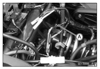
- Disconnect the speed sensor connector and connect the harness adapter [A] between these connectors.
Special Tool - Throttle Sensor Setting Adapter #1: 57001 -1400
- Connect a digital meter to the harness adapter leads.
Speed Sensor Input Voltage
Connections to Adapter:
Digital Meter (+) → BL (sensor P) lead
Digital Meter (-) → BK/BL (sensor BK) lead
- Measure the input voltage with the engine stopped and with the connector joined.
- Turn the ignition switch ON.
Input Voltage
Standard: About DC 9 - 11 V
- Turn the ignition switch OFF.
If the reading is within the standard, check the output voltage (see Speed Sensor Output Voltage Inspection).
If the reading is out of the standard, remove the ECU and check the wiring for continuity between main harness connectors.
- Disconnect the ECU and sensor connectors.
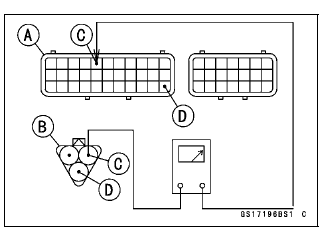
Wiring Inspection
ECU Connector [A] ←→
Speed Sensor Connector [B]
BL lead (ECU terminal 5) [C]
BR/BK lead (ECU terminal 33) [D]
If the wiring is good, check the ECU for its ground and power supply (see ECU Power Supply Inspection).
If the ground and power supply are good, replace the ECU (see ECU Removal/Installation).
Speed Sensor Output Voltage Inspection
- Using the stand, raise the rear wheel off the ground.
- Measure the output voltage at the speed sensor in the same way as input
voltage inspection, note the following.
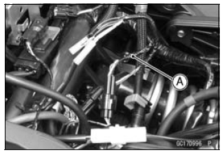
- Disconnect the speed sensor connector and connect the harness adapter [A] between these connectors.
Special Tool - Throttle Sensor Setting Adapter #1: 57001 -1400
Speed Sensor Output Voltage
Connections to Adapter:
Digital Meter (+) → Y/W (sensor Y) lead
Digital Meter (-) → BK/BL (sensor BK) lead
- Measure the output voltage with the engine stopped and with the connector joined.
- Turn the ignition switch ON.
Output Voltage
Standard:
Less than DC 0.6 V or over than 4.8 V at ignition switch ON and 0 km/h
NOTE
- Rotate the rear wheel by hand, confirm the output voltage will be raise or lower.
- Turn the ignition switch OFF.
If the reading is out of the standard, check the speed sensor (see Speed Sensor Inspection in the Electrical System chapter).
If the reading is within the standard, remove the ECU and check the wiring for continuity between main harness connectors.
- Disconnect the ECU and sensor connectors.
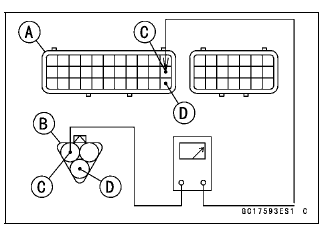
Wiring Inspection
ECU Connector [A] ←→
Speed Sensor Connector [B]
P lead (ECU terminal 22) [C]
BR/BK lead (ECU terminal 33) [D]
If the wiring is good, check the ECU for its ground and power supply (see ECU Power Supply Inspection).
If the ground and power supply are good, replace the ECU (see ECU Removal/Installation).
Speed Sensor Circuit
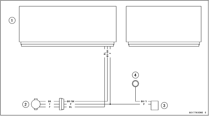
- ECU
- Speed Sensor
- Meter Unit
- Meter Ground
See also:
 Kawasaki Z1000SX - Service manual > Intake Air Pressure Sensor #2 (Service Code 16)
Intake Air Pressure Sensor #2 Removal NOTICE Never drop the intake air pressure sensor #2 especially on a hard surface. Such a shock to the sensor can damage it. Remove the air cleaner housing (see Air Cleaner Housing Removal). Disconnect the sensor connector [A]. Remove the intake air pressure sensor #2 [A] from the rubber damper [B] in the bracket and separate the vacuum hose [C].
Kawasaki Z1000SX - Service manual > Vehicle-down Sensor (Service Code 31)
This sensor has a weight [A] with two magnets inside, and sends a signal to the ECU. But when the motorcycle banks 60 - 70º or more to either side (in fact falls down), the weight turns and the signal changes. The ECU senses this change, and stops the fuel pump relay, the fuel injectors and the ignition system.
 Rider's Manual BMW R 1250 GS GSA
 Owner's Manual Harley-Davidson Sportster XL1200X Forty-Eight
 Owner's Manual Honda CBR650R
 Service manual Honda CBR650
 Owner's Manual Honda PCX125
 Owner's Manual Kawasaki Z1000SX
 Service manual Kawasaki Z1000SX
 Owner's Manual Lexmoto Echo
 Owner's Manual Royal Enfield Interceptor 650
 Service manual Royal Enfield Interceptor 650
 Owner's Manual Yamaha MT-07