 Kawasaki Z1000SX - Service manual > Intake Air Pressure Sensor #2 (Service Code 16)
Intake Air Pressure Sensor #2 Removal
NOTICE Never drop the intake air pressure sensor #2 especially on a hard surface. Such a shock to the sensor can damage it.
- Remove the air cleaner housing (see Air Cleaner Housing Removal).
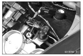
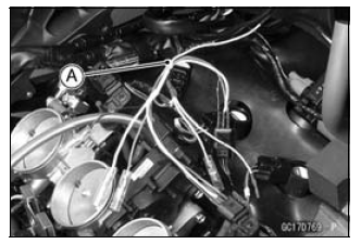
- Disconnect the sensor connector [A].
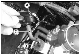
- Remove the intake air pressure sensor #2 [A] from the rubber damper [B] in the bracket and separate the vacuum hose [C].
Intake Air Pressure Sensor #2 Installation
NOTE
- The intake air pressure sensor #2 is the same part as the intake air pressure sensor #1.
- Installation is the reverse of removal.
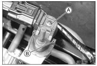
- Position the intake air pressure sensor #2 [A] between the projection [B] on the rubber damper.
Intake Air Pressure Sensor #2 Input Voltage Inspection
NOTE
- Be sure the battery is fully charged.
- Turn the ignition switch OFF.
- Remove the air cleaner housing (see Air Cleaner Housing Removal).
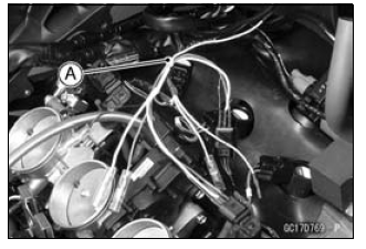
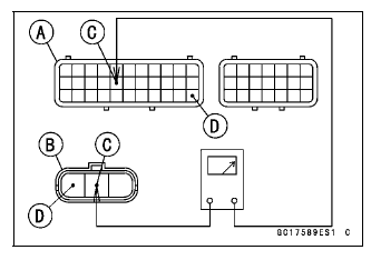
- Disconnect the intake air pressure sensor #2 connector and connect the
harness adapter [A] between these connectors.
[B] Main Harness
[C] Intake Air Pressure Sensor #2
Special Tool - Measuring Adapter: 57001-1700
- Connect a digital meter [D] to the harness adapter leads.
Intake Air Pressure Sensor #2 Input Voltage
Connections to Adapter:
Digital Meter (+) → R (sensor BL) lead
Digital Meter (-) → BK (sensor BR/BK) lead
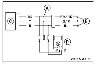
- Measure the input voltage with the engine stopped and with the connector joined.
- Turn the ignition switch ON.
Input Voltage
Standard: DC 4.75 - 5.25 V
- Turn the ignition switch OFF.
If the reading is within the standard, check the output voltage (see Intake Air Pressure Sensor #2 Output Voltage Inspection).
If the reading is out of the standard, remove the ECU and check the wiring for continuity between main harness connectors.
Special Tool - Hand Tester: 57001-1394
- Disconnect the ECU and sensor connectors.
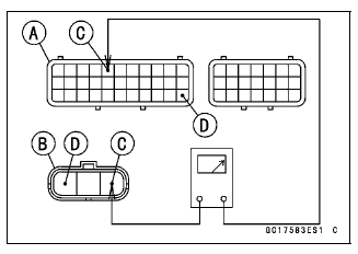
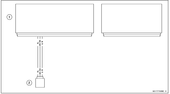
Wiring Continuity Inspection
ECU Connector [A] ←→
Intake Air Pressure Sensor #2 Connector [B]
BL lead (ECU terminal 5) [C]
BR/BK lead (ECU terminal 33) [D]
If the wiring is good, check the ECU for its ground and power supply (see ECU Power Supply Inspection).
If the ground and power supply are good, replace the ECU (see ECU Removal/Installation).
Intake Air Pressure Sensor #2 Output Voltage Inspection
- Measure the output voltage at the intake air pressure sensor #2 in the
same way as input voltage inspection, note the following.
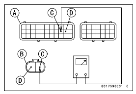
- Disconnect the intake air pressure sensor #2 connector and connect
the harness adapter [A] between these connectors.
[B] Main Harness
[C] Intake Air Pressure Sensor #2
[D] Digital Meter
- Disconnect the intake air pressure sensor #2 connector and connect
the harness adapter [A] between these connectors.
Special Tool - Measuring Adapter: 57001-1700
Intake Air Pressure Sensor #2 Output Voltage
Connections to Adapter:
Digital Meter (+) → Y (sensor G/W) lead
Digital Meter (-) → BK (sensor BR/BK) lead
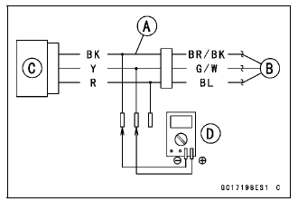
- Measure the output voltage with the engine stopped and with the connector joined.
- Turn the ignition switch ON.
Output Voltage
Usable Range:
DC 3.80 - 4.20 V at standard atmospheric pressure (101.32 kPa, 76 cmHg
absolute)
NOTE
- The output voltage changes according to the local atmospheric pressure.
- Turn the ignition switch OFF.
If the reading is out of the usable range, replace the sensor.
If the reading is within the usable range, remove the ECU and check the wiring for continuity between main harness connector.
Special Tool - Hand Tester: 57001-1394
- Disconnect the ECU and sensor connectors.
Wiring Continuity Inspection
ECU Connector [A] ←→
Intake Air Pressure Sensor #2 Connector [B]
G/W lead (ECU terminal 16) [C]
BR/BK lead (ECU terminal 33) [D]
If the wiring is good, check the sensor for various vacuum (see Intake Air Pressure Sensor #1 Output Voltage Inspection).
Intake Air Pressure Sensor #2 Circuit
- ECU
- Intake Air Pressure Sensor #2
Crankshaft Sensor (Service Code 21)
The crankshaft sensor has no power source, and when the engine stops, the crankshaft sensor generates no signals.
Crankshaft Sensor Removal/Installation
- Refer to the Crankshaft Sensor Removal/Installation in the Electrical System chapter.
Crankshaft Sensor Resistance Inspection
- Refer to the Crankshaft Sensor Inspection in the Electrical System
chapter.
If the reading is within the standard, check the peak voltage (see Crankshaft Sensor Peak Voltage Inspection).
Crankshaft Sensor Peak Voltage Inspection
- Refer to the Crankshaft Sensor Peak Voltage Inspection in the Electrical
System chapter.
If the reading is within the standard, remove the ECU and check the wiring for continuity between main harness connectors.
- Disconnect the ECU and sensor connectors.
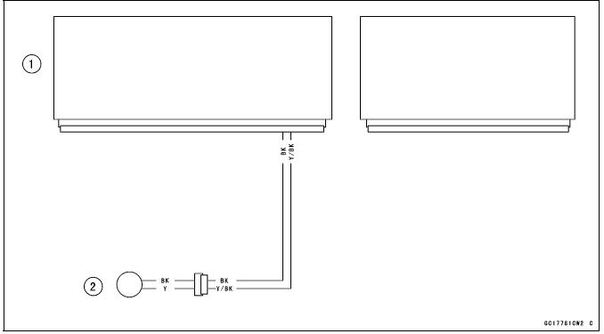
Wiring Inspection
ECU Connector [A] ←→
Crankshaft Sensor Connector [B]
Y/BK lead (ECU terminal 20) [C]
BK lead (ECU terminal 21) [D]
If the wiring is good, check the ECU for its ground and power supply (see ECU Power Supply Inspection).
If the ground and power supply are good, replace the ECU (see ECU Removal/Installation).
Crankshaft Sensor Circuit
- ECU
- Crankshaft Sensor
See also:
 Kawasaki Z1000SX - Service manual > Water Temperature Sensor (Service Code 14)
Water Temperature Sensor Removal/Installation NOTICE Never drop the water temperature sensor especially on a hard surface. Such a shock to the sensor can damage it. Drain the coolant (see Coolant Change in the Periodic Maintenance chapter). Remove: Left Lower Fairing (see Lower Fairing Removal in the Frame chapter) Connector [A] Water Temperature Sensor [B] Replace the gasket with a new one, and tighten the water temperature sensor.
Kawasaki Z1000SX - Service manual > Speed Sensor (Service Code 24, 25)
Speed Sensor Removal/Installation Refer to the Speed Sensor Removal/Installation in the Electrical System chapter. Speed Sensor Inspection Refer to the Speed Sensor Inspection in the Electrical System chapter.
 Rider's Manual BMW R 1250 GS GSA
 Owner's Manual Harley-Davidson Sportster XL1200X Forty-Eight
 Owner's Manual Honda CBR650R
 Service manual Honda CBR650
 Owner's Manual Honda PCX125
 Owner's Manual Kawasaki Z1000SX
 Service manual Kawasaki Z1000SX
 Owner's Manual Lexmoto Echo
 Owner's Manual Royal Enfield Interceptor 650
 Service manual Royal Enfield Interceptor 650
 Owner's Manual Yamaha MT-07