 Kawasaki Z1000SX - Service manual > Water Temperature Sensor (Service Code 14)
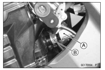
Water Temperature Sensor Removal/Installation
NOTICE Never drop the water temperature sensor especially on a hard surface. Such a shock to the sensor can damage it.
- Drain the coolant (see Coolant Change in the Periodic Maintenance chapter).
- Remove:
Left Lower Fairing (see Lower Fairing Removal in the Frame chapter)
Connector [A]
Water Temperature Sensor [B] - Replace the gasket with a new one, and tighten the water temperature
sensor.
Torque - Water Temperature Sensor: 30 N*m (3.0 kgf*m, 22 ft*lb)
- Fill the engine with coolant and bleed the air from the cooling system (see Coolant Change in the Periodic Maintenance chapter).
Water Temperature Sensor Output Voltage Inspection
NOTE
- Be sure the battery is fully charged.
- Turn the ignition switch OFF.
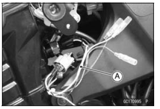
- Remove the left lower fairing (see Lower Fairing Removal in the Frame chapter)
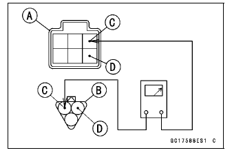
- Disconnect the water temperature sensor connector and connect the
harness adapter [A] between these connectors as shown.
Sub Harness [B]
Water Temperature Sensor [C]
Special Tool - Measuring Adapter: 57001-1700
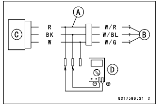
- Connect a digital meter [D] to the harness adapter leads.
Water Temperature Sensor Output Voltage
Connections to Adapter:
Digital Meter (+) → R (sensor W/R) lead
Digital Meter (-) → BK (sensor W/BL) lead
- Measure the output voltage with the engine stopped and with the connector joined.
- Turn the ignition switch ON.
Output Voltage
Standard: About DC 2.80 - 2.97 V at 20ºC (68ºF)
NOTE
- The output voltage changes according to the coolant temperature in the engine.
- Turn the ignition switch OFF.
If the reading is within the standard, check the ECU for its ground and power supply (see ECU Power Supply Inspection).
If the ground and power supply are good, replace the ECU (see ECU Removal/Installation).
If the reading is out of the standard, remove the ECU and check the wiring for continuity between main and sub harness connectors.
- Disconnect the ECU and sensor connectors.
Wiring Inspection
ECU Connector [A] ←→
Sub Harness Connector [B]
O lead (ECU terminal 29) [C]
BR/BK lead (ECU terminal 33) [D]
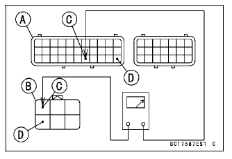
Sub Harness Connector [A] ←→
Sub Harness Connector [B]
W/R lead [C]
W/BL lead [D]
If the wiring is good, check the water temperature sensor resistance (see Water Temperature Sensor Resistance Inspection).
Water Temperature Sensor Resistance Inspection
- Refer to the Water Temperature Sensor Inspection in the Electrical
System chapter.
If the reading is within the standard, but the problem still exists, replace the ECU (see ECU Removal/Installation).
Water Temperature Sensor Circuit
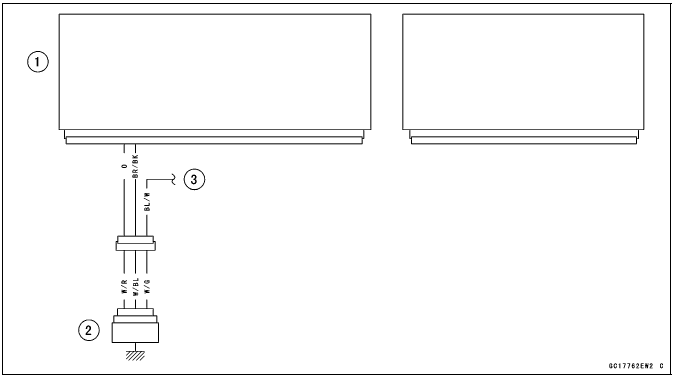
- ECU
- Water Temperature Sensor
- To Meter Unit
See also:
 Kawasaki Z1000SX - Service manual > Intake Air Temperature Sensor (Service Code 13)
Intake Air Temperature Sensor Removal/Installation NOTICE Never drop the intake air temperature sensor especially on a hard surface. Such a shock to the sensor can damage it. Remove the fuel tank (see Fuel Tank Removal). Disconnect the connector [A] from the intake air temperature sensor [B]. Remove: Screw [C] Intake Air Temperature Sensor Be sure to install the O-ring [A]. Install the intake air temperature sensor. Tighten: Torque - Intake Air Temperature Sensor Mounting Screw: 1.2 N*m (0.12 kgf*m, 11 in*lb)
Kawasaki Z1000SX - Service manual > Intake Air Pressure Sensor #2 (Service Code 16)
Intake Air Pressure Sensor #2 Removal NOTICE Never drop the intake air pressure sensor #2 especially on a hard surface. Such a shock to the sensor can damage it. Remove the air cleaner housing (see Air Cleaner Housing Removal). Disconnect the sensor connector [A]. Remove the intake air pressure sensor #2 [A] from the rubber damper [B] in the bracket and separate the vacuum hose [C].
 Rider's Manual BMW R 1250 GS GSA
 Owner's Manual Harley-Davidson Sportster XL1200X Forty-Eight
 Owner's Manual Honda CBR650R
 Service manual Honda CBR650
 Owner's Manual Honda PCX125
 Owner's Manual Kawasaki Z1000SX
 Service manual Kawasaki Z1000SX
 Owner's Manual Lexmoto Echo
 Owner's Manual Royal Enfield Interceptor 650
 Service manual Royal Enfield Interceptor 650
 Owner's Manual Yamaha MT-07