 Kawasaki Z1000SX - Service manual > Swingarm
Swingarm Removal
- Remove:
Rear Brake Hose Lower End (see Rear Caliper Removal in the Brakes chapter)
Rear Wheel (see Rear Wheel Removal in the Wheels/Tires chapter)
Mud Guard (see Mad Guard Removal in the Frame chapter)
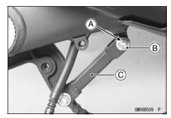
Rocker Arm (see Rocker Arm Removal) - Remove:
Cotter Pin [A]
Bolt and Nut [B] - Move the torque link [C] downward.
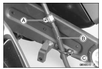
- Remove:
Brake Hose Clamp Bolt [A] - Clear the brake hose [B] from the guide [C] on the swingarm.
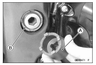
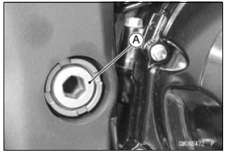
- Unscrew the swingarm pivot shaft nut [A].
- Using the swingarm pivot nut wrench [A], loosen the swingarm pivot
adjusting collar locknut [B].
Special Tool - Swingarm Pivot Nut Wrench: 57001-1597
- Turn the swingarm pivot shaft [A] counterclockwise to free the adjusting
collar from the swingarm.
- Make the gap between the adjusting collar and swingarm.
- Pull out the pivot shaft to the right side and remove the swingarm.
Swingarm Installation
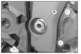
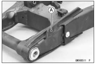
- Visually inspect the chain guide [A].
Replace the chain guide if it shows any signs of abnormal wear or damage.
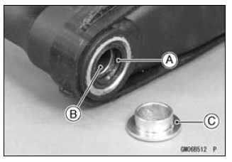
- Apply grease to the lips of the grease seals [A].
- Be sure to install the grease seals and sleeve [B] to the swingarm.
- Fit the collar [C] on the grease seal of the left side.
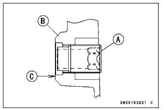
- Screw the swingarm pivot adjusting collar [A] into the frame [B] so that the collar does not project the swingarm mating surface [C].
- Install the swingarm and insert the swingarm pivot shaft [A] into the adjusting collar [B] from the right side, and tighten the pivot shaft.
NOTE
- Tighten the swingarm pivot shaft until the clearance [C] between the ball bearing [D] and collar comes to 0 mm (0 in.).
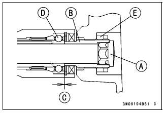
Torque - Swingarm Pivot Shaft: 20 N*m (2.0 kgf*m, 15 ft*lb)
- Using the swingarm pivot nut wrench, tighten the swingarm pivot adjusting collar locknut [E].
Special Tool - Swingarm Pivot Nut Wrench: 57001-1597
Torque - Swingarm Pivot Adjusting Collar Locknut: 98 N*m (10 kgf*m, 72 ft*lb)
- Tighten the swingarm pivot shaft nut.
Torque - Swingarm Pivot Shaft Nut: 108 N*m (11.0 kgf*m, 79.7 ft*lb)
- Move the swingarm up and down to check for abnormal friction.
- Install the removed parts (see appropriate chapters).
Swingarm Bearing Removal
- Remove:
Swingarm (see Swingarm Removal)
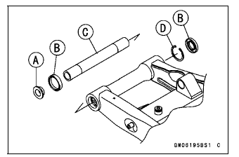
Collar [A]
Grease Seals [B]
Sleeve [C]
Circlip (Right Side) [D]
Special Tool - Inside Circlip Pliers: 57001-143
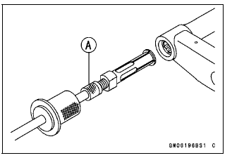
- Remove the ball bearing and needle bearings.
Special Tool - Oil Seal & Bearing Remover [A]: 57001-1058
Swingarm Bearing Installation
- Replace the needle bearings [A], ball bearing [B], grease seals [C] and circlip [D] with new ones.
- Install the needle bearings as shown in the figure.
[E] Left Side
[F] Right Side
[G] 27 mm (1.1 in.)
[H] 9.5 mm (0.37 in.)
[I] 29.5 mm (1.16 in.)
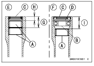
NOTE
- Install the needle bearings so that the marked side faces out.
Special Tool - Needle Bearing Driver,
28: 57001-1610
- Press in the ball bearing until it bottomed.
Special Tool - Bearing Driver Set: 57001-1129
- Install the circlip.
Special Tool - Inside Circlip Pliers: 57001-143
- Press in the grease seals so that seal surface is flushed with the end
of housing.
Special Tool - Bearing Driver Set: 57001-1129
Swingarm Bearing, Sleeve Inspection
NOTICE Do not remove the bearings for inspection. Removal may damage them.
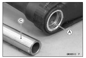
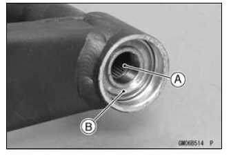
- Inspect the needle bearings [A] and ball bearing [B] installed in the
swingarm.
- The rollers and ball in a bearing normally wear very little, and wear is difficult to measure. Instead of measuring, visually inspect the bearing for abrasion, discoloration, or other damage.
If the needle bearing and sleeve [C] show any sings of abnormal wear, discoloration, or damage, replace them as a set.
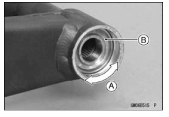
- Turn the bearing in the swingarm back and forth [A] while checking for
plays, roughness, or binding.
If bearing play, roughness, or binding is found, replace the bearing.
- Examine the bearing seal [B] for tears or leakage.
If the seal is torn or is leaking, replace the bearing.
Swingarm Bearing Lubrication
NOTE
- Since the bearings are packed with grease and sealed, lubrication is not required.
Chain Guide Inspection
- Refer to the Chain Guide Wear Inspection in the Periodic Maintenance chapter.
See also:
 Kawasaki Z1000SX - Service manual > Rear Shock Absorber
Rebound Damping Force Adjustment To adjust the rebound damping force, turn the lower damping adjuster [A] to the desired position, until you feel a click. The standard adjuster setting is the 1 1/4 turns out from the fully clockwise position.
Kawasaki Z1000SX - Service manual > Tie-Rod, Rocker Arm
Tie-Rod Removal Remove: Mud Guard (see Mud Guard Removal in the Frame chapter) Squeeze the brake lever slowly and hold it with a band [A]. Raise the rear wheel off the ground with the jack (see Rear Shock Absorber Removal).
 Rider's Manual BMW R 1250 GS GSA
 Owner's Manual Harley-Davidson Sportster XL1200X Forty-Eight
 Owner's Manual Honda CBR650R
 Service manual Honda CBR650
 Owner's Manual Honda PCX125
 Owner's Manual Kawasaki Z1000SX
 Service manual Kawasaki Z1000SX
 Owner's Manual Lexmoto Echo
 Owner's Manual Royal Enfield Interceptor 650
 Service manual Royal Enfield Interceptor 650
 Owner's Manual Yamaha MT-07