 Kawasaki Z1000SX - Service manual > Switches and Sensors
Brake Light Timing Inspection
- Refer to the Brake Light Switch Operation Inspection in the Periodic Maintenance chapter.
Brake Light Timing Adjustment
- Refer to the Brake Light Switch Operation Inspection in the Periodic Maintenance chapter.
Switch Inspection
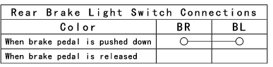
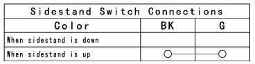
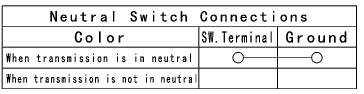
- Using a hand tester, check to see that only the connections shown in the
table have continuity (about zero ohms).
- For the switch housings and the ignition switch, refer to the tables in the Wiring Diagram.
If the switch has an open or short, repair it or replace it with a new one.
Special Tool - Hand Tester: 57001-1394
Rear Brake Light Switch Connections
Sidestand Switch Connections
Neutral Switch Connections
Oil Pressure Switch Connections*
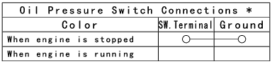
*: Engine lubrication system is in good condition.
Water Temperature Sensor Inspection
- Remove the water temperature sensor (see Water Temperature Sensor Removal/Installation in the Fuel System (DFI) chapter).
- Suspend the sensor [A] in a container of coolant so that the threaded portion is submerged.
- Suspend an accurate thermometer [B] with temperature sensing portions [C] located in almost the same depth.
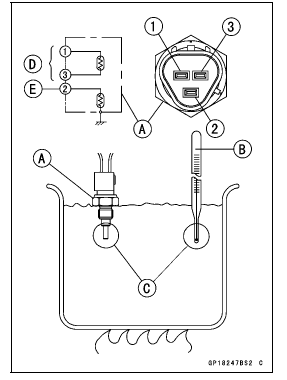
NOTE
- The sensor and thermometer must not touch the container side or bottom.
- Place the container over a source of heat and gradually raise the temperature of the coolant while stirring the coolant gently.
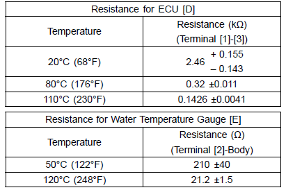
- Using the hand tester, measure the internal resistance of the sensor.
- The sensor sends electric signals to the ECU and coolant temperature gauge in the meter unit.
- Measure the resistance across the terminals and the body (for the gauge) at the temperatures shown in the table.
If the hand tester does not show the specified values, replace the sensor.
Water Temperature Sensor
Speed Sensor Removal
NOTICE Never drop the sensor especially on a hard surface.
Such a shock to the sensor can damage it.
- Support the fuel tank with suitable bar (see Fuel Tank Removal in the Fuel System (DFI) chapter).
- Remove:
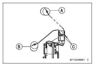
Speed Sensor Connector (Disconnect) [A]
Engine Sprocket Cover (see Engine sprocket Cover Removal in the Final Drive chapter)
Speed Sensor
Speed Sensor Installation
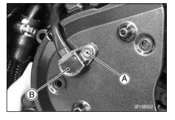
- Apply a non-parmanent locking agent to the speed sensor mounting bolt [A].
- Install the speed sensor [B] to the inner engine sprocket cover.
- Tighten:
Torque - Speed Sensor Mounting Bolt: 6.9 N*m (0.70 kgf*m, 61 in*lb)
- Install the engine sprocket cover (see Engine Sprocket Cover Installation in the Final Drive chapter).
- Connect the speed sensor lead connector.
- Install the fuel tank (see Fuel Tank Installation in the Fuel System (DFI) chapter).
- Confirm that the drain hose and clamp are installed securely and run the hose correctly (see Cable, Wire, and Hose Routing section in the Appendix chapter).
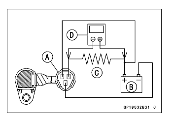
Speed Sensor Inspection
- Remove the speed sensor (see Speed Sensor Removal).
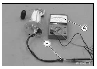
- Connect the speed sensor connector [A] with the battery [B], 10 kΩ resistor [C] and hand tester [D] as shown in the figure.
- Set the tester to the DC 25 V range.
Special Tool - Hand Tester: 57001-1394
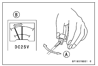
- Trace [A] of the speed sensor surface with the screwdriver.
- Then the tester indicator should flick [B].
If the tester indicator does not flick, replace the speed sensor.
Oxygen Sensor Removal (Equipped Models)
NOTICE Never drop the sensor especially on a hard surface.
Such a shock to the sensor can damage it.
NOTICE Do not pull strongly, twist, or bend the oxygen sensor lead. This may cause the wiring open.
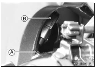
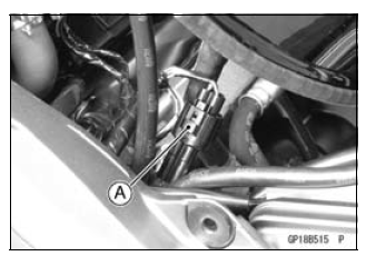
- Clear the oxygen sensor lead from the clamp [A].
- Disconnect the oxygen sensor lead connector [B].
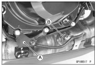
- Clear the oxygen sensor lead from the clamp [A].
- Remove the oxygen sensor [B].
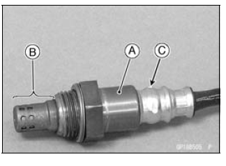
Oxygen Sensor Installation (Equipped Models)
NOTICE Never drop the oxygen sensor [A] especially on a hard surface. Such a shock to the unit can damage it. Do not touch the sensing part [B] and filter holes [C] of the sensor to prevent oil contact. Oil contamination from hands can reduce sensor performance.
- Tighten:
Torque - Oxygen Sensor: 44 N*m (4.5 kgf*m, 32 ft*lb) - Run the oxygen sensor lead correctly (see Cable, Wire, and Hose Routing section in the Appendix chapter).
Oxygen Sensor Inspection (Equipped Models)
- Refer to the Oxygen Sensor Inspection in the Fuel System (DFI) chapter.
Fuel Level Sensor Inspection
- Remove:
Fuel Pump (see Fuel Pump Removal in the Fuel System (DFI) chapter) - Check that the float moves up and down smoothly without binding. It
should go down under its own weight.
If the float does not move smoothly, replace the fuel pump.
Float in Full Position [A]
Float in Empty Position [B]
Float Arm Stoppers [C]
- Using the hand tester [A], measure the resistance across the terminals
in the fuel level sensor lead connector [B].
Special Tools -
Hand Tester: 57001-1394
Needle Adapter set: 57001-1457
If the tester readings are not as specified, or do not change smoothly according as the float moves up and down, replace the fuel pump.
Fuel Level Sensor Resistance
Standard:
Full position: 9.6 - 12.4 Ω
Empty position: 222 - 228 Ω
See also:
 Kawasaki Z1000SX - Service manual > Immobilizer System (Equipped Models)
This motorcycle is equipped with an immobilizer system to protect the motorcycle from theft. This system provides a theft proof device by means of matching a code between the inbuilt key transponder and ECU (Electronic Control Unit). If the code does not match, ignition system, injectors, subthrottle valve actuator and exhaust butterfly valve actuator will not operate and the engine will not start.
Kawasaki Z1000SX - Service manual > Relay Box
The relay box [A] has relays and diodes. The relays and diodes can not be removed. Relay Box Removal
 Rider's Manual BMW R 1250 GS GSA
 Owner's Manual Harley-Davidson Sportster XL1200X Forty-Eight
 Owner's Manual Honda CBR650R
 Service manual Honda CBR650
 Owner's Manual Honda PCX125
 Owner's Manual Kawasaki Z1000SX
 Service manual Kawasaki Z1000SX
 Owner's Manual Lexmoto Echo
 Owner's Manual Royal Enfield Interceptor 650
 Service manual Royal Enfield Interceptor 650
 Owner's Manual Yamaha MT-07