 Kawasaki Z1000SX - Service manual > Immobilizer System (Equipped Models)
This motorcycle is equipped with an immobilizer system to protect the motorcycle from theft. This system provides a theft proof device by means of matching a code between the inbuilt key transponder and ECU (Electronic Control Unit). If the code does not match, ignition system, injectors, subthrottle valve actuator and exhaust butterfly valve actuator will not operate and the engine will not start.
Abstract
- Do not keep more than one immobilizer key of any system on a key ring. Jamming of the key code signal may occur and the operation of the system may be affected.
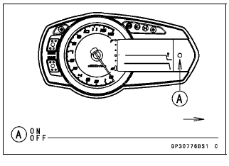
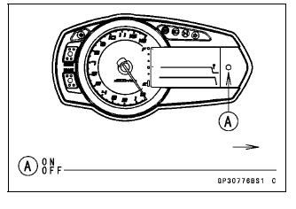
- The warning indicator light (LED) will flash for a period of 24 hours once the ignition switch has been switched off and the key removed. This flashing can be set to on or off as desired by holding the left and right buttons down for two seconds within twenty seconds of switching the ignition off.
- If all coded keys are lost the ECU and ignition switch will have to be replaced.
- The immobilizer system can not function until the ignition key code is registered in the ECU.
- A total of five keys can be registered in the ECU at any one time.
Operational Cautions
1. Do not put two keys of any immobilizer system on the same key ring.
2. Do not submerge any key in water.
3. Do not expose any key to excessively high temperature.
4. Do not place any key close to magnet.
5. Do not place a heavy item on any key.
6. Do not grind any key or alter its shape.
7. Do not disassemble the plastic part of any key.
8. Do not drop the key and/or apply any shocks to the key.
9. When a ignition key is lost, the user should go to his dealer to invalidate the lost key registration in the ECU.
10.When the all ignition key is lost, the user should go to his dealer and have a new ECU installed and register the ignition keys.
NOTE
- No.9 and 10 are strongly recommended to the customer to ensure security of the motorcycle.
Key Registration
Case 1: When additional spare ignition key is required.
- Prepare a new spare ignition key.
- Cut the key in accordance with the shape of the current ignition key.
- Remove:
Front Seat (see Front Seat Removal in the Frame chapter) - Remove the immobilizer/Kawasaki diagnostic system connector cap [A].
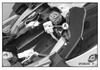
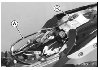
- Connect the key registration adapter [A] and key registration unit [B].
Special Tools -
Key Registration Unit: 57001-1582
Key Registration Adapter: 57001-1746
- Insert the registered ignition key into the ignition switch, and turn it to ON.
Verified
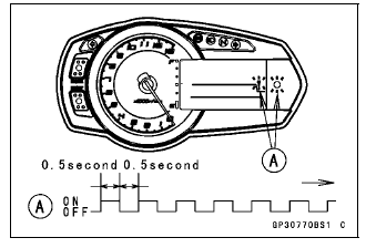
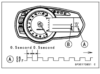
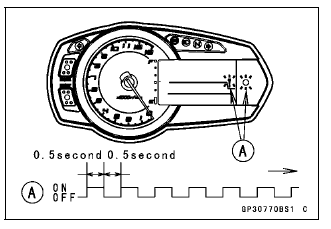
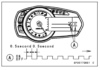
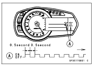
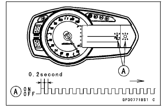
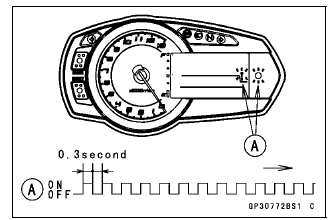
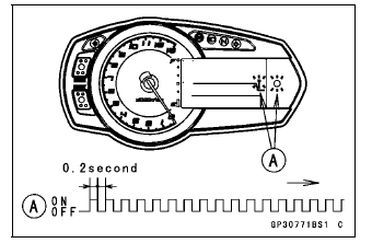
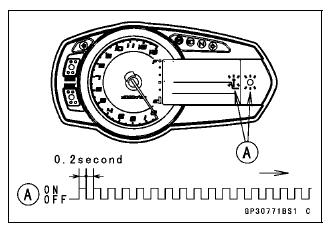
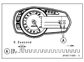
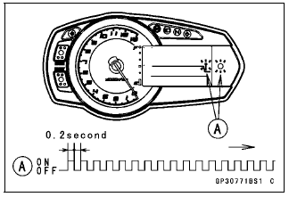
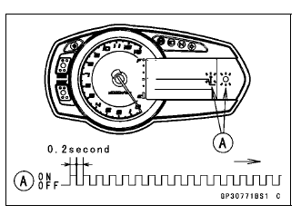
- The warning indicator light (LED) and the immobilizer warning symbol [A] blink to display the registration mode (go to the next step).
Not Verified
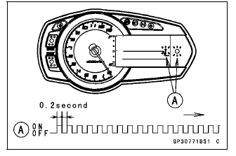
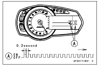
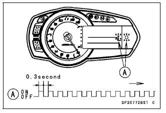
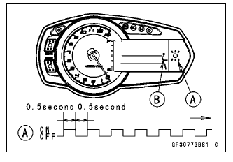
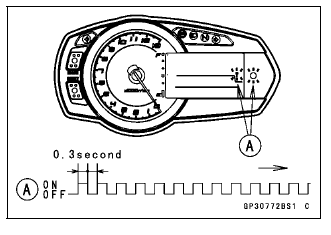
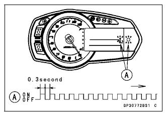
- The warning indicator light (LED) and the immobilizer warning symbol [A]
blink to display the collation error (refer to the following failure
illustrations).
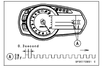
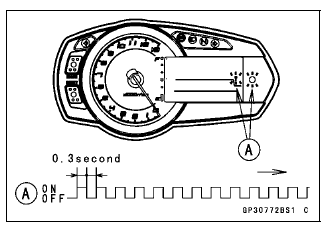
Immobilizer Amplifier Failure

Registered Ignition Key Collation Error
- Turn to OFF the ignition switch and remove the registered ignition key.
If there are other registered ignition keys, they should all do the procedure above.
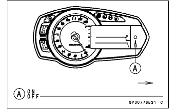
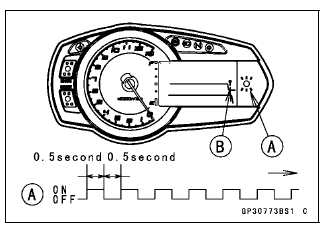
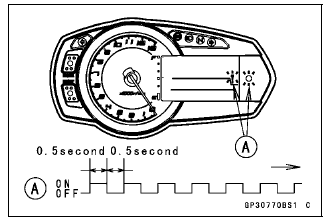
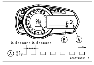
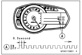
- The warning indicator light (LED) [A] then blinks for 15 seconds; it means the ECU is in the registration mode.
- The immobilizer warning symbol [B] disappears.
- After 15 seconds, the ECU ends the registration mode and stops blinking the warning indicator light (LED).
NOTE
- Insert and turn on the next key between 15 seconds that the ECU is in the registration mode.
- When a registration mode was ended, do the registered ignition key(s) verification procedure over again to restart it. This applies to all ignition key registration.
- Insert the ignition key 1 into the ignition switch, and turn it to ON.
NOTE
- Keep other ignition keys away from the immobilizer antenna.
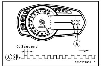
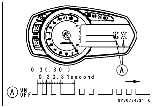
- If there is any problem in the registration, the warning indicator light
(LED) and the immobilizer warning symbol [A] blink to display the collation
error.
Immobilizer Amplifier Failure
When Registered Ignition Key is Inserted.

Ignition Key Collation Error
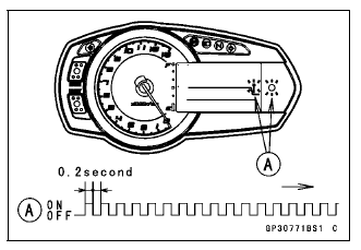
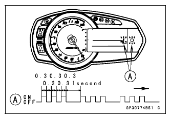
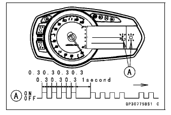
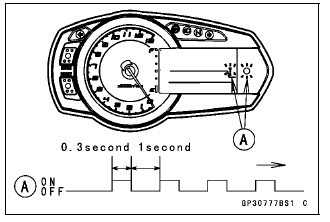
- The ignition key 1 is successfully registered in the ECU.
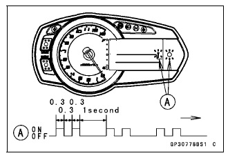
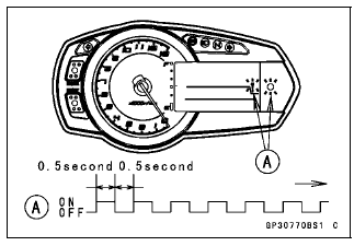
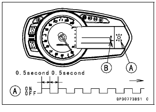
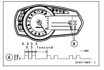
- The warning indicator light (LED) and the immobilizer warning symbol [A] blink 3 times and stop for 1 second and then repeat this cycle.
- Turn to OFF the ignition switch and remove the ignition key 1.
- The immobilizer warning symbol [A] disappears.
- The warning indicator light (LED) then blinks for 15 seconds.
- After 15 seconds, the ECU ends the registration mode and stops blinking the warning indicator light (LED).
NOTE
- This procedure registered the registered ignition key and one ignition key.
If more keys registration is needed, go to next procedures within the registration mode.
- Insert the ignition key 2 to the ignition switch and turn it to ON.
- If there is any problem in the registration, the warning indicator
light (LED) and the immobilizer warning symbol [A] blink to display the
collation error.
Immobilizer Amplifier Failure
- If there is any problem in the registration, the warning indicator
light (LED) and the immobilizer warning symbol [A] blink to display the
collation error.
When Registered Ignition Key is Inserted.
Ignition Key Collation Error
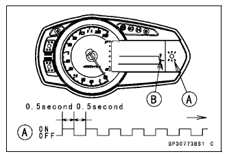
- The ignition key 2 is successfully registered in the ECU.
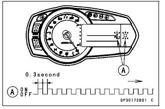
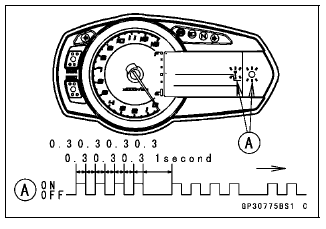
- The warning indicator light (LED) and the immobilizer warning symbol [A] blink 4 times and stop for 1 second and then repeat this cycle.
- This procedure has registered the 2 ignition keys.
- Continue with the procedure if neccesary to register an additional one ignition key.
NOTE
- The ECU can store up the five key codes.
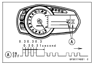
Ignition Key Indicator Flashes
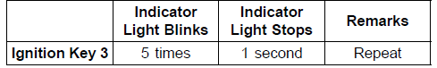
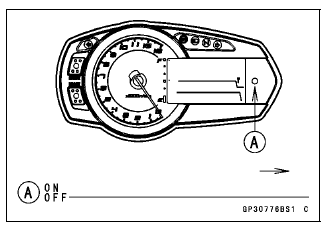
- Turn to OFF the ignition switch and wait for period of more than 15 seconds.
- The registration mode automatically ends.
- The warning indicator light (LED) [A] goes off.
- Remove the key registration unit, key registration adapter and install the immobilizer/Kawasaki diagnostic system connector cap.
NOTE
- Turn the ignition switch to ON with the registered ignition key.
- Check that the engine can be started using all registered ignition keys.
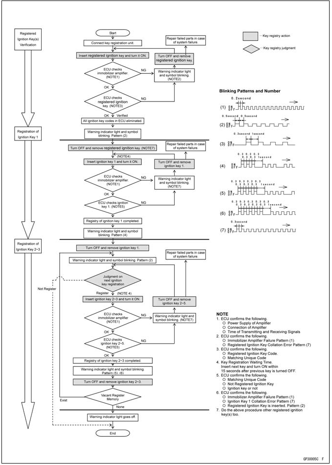
Spare Ignition Key Registration Flow Chart
Case 2: When the ignition switch is faulty and has to be replaced.
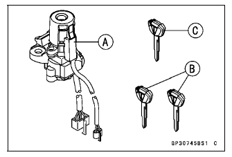
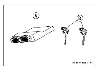
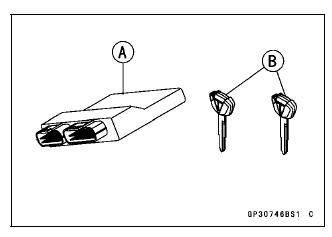
- Prepare a new ignition switch [A] and two new ignition keys [B].
- These parts are available as a set. Prepare the current registered ignition key [C].
- Remove:
Ignition Switch (see Immobilizer System Parts Replacement)
Front Seat (see Front Seat Removal in the Frame chapter) - Remove the immobilizer/Kawasaki diagnostic system connector cap.
- Connect the key registration adapter [A] and key registration unit [B].
Special Tools -
Key Registration Unit: 57001-1582
Key Registration Adapter: 57001-1746
- Connect:
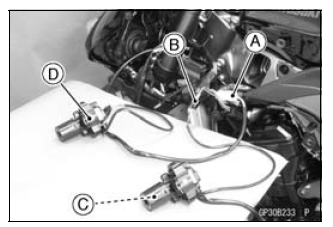
New Ignition Switch Lead Connector [A]
Immobilizer Antenna Lead Connector [B] (of Current Ignition Switch)
NOTE
- Keep the antenna [C] more than 15 cm (5.9 in.) from the new ignition switch [D].
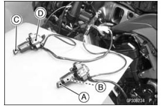
- Insert the current registered ignition key [A] into the current ignition switch [B].
- Insert the new ignition key 1 [C] into the new ignition switch [D], and turn it to ON.
Verified
- The warning indicator light (LED) and the immobilizer warning symbol [A] blink to display the ECU is in the registration mode (go to the next step).
Not Verified
- The warning indicator light (LED) and the immobilizer warning symbol [A] blink to display the collation error.
Immobilizer Amplifier Failure
Registered Ignition Key Collation Error
- Turn to OFF the ignition switch and remove the new ignition key 1.
- The immobilizer warning symbol [B] disappears.
- The warning indicator light (LED) [A] then blinks for 15 seconds; it means the ECU is in the registration mode.
- After 15 seconds, the ECU ends the registration mode and stops blinking the warning indicator light (LED).
- Disconnect the antenna lead connector of the current ignition switch and connect the antenna lead connector of the new ignition switch [A].
- Insert the ignition key 1 [B] again into the new ignition switch, and turn it to ON.
NOTE
- Insert and turn on the ignition key within 15 seconds that the ECU is in the registration mode.
- When a registration mode was ended, do the registered ignition key verification procedure over again to restart it. This applies to all ignition key registration.
- Keep other ignition keys away from the immobilizer antenna.
- If there is any problem in the registration, the warning indicator light (LED) and the immobilizer warning symbol [A] blink to display the collation error.
Immobilizer Amplifier Failure
When Registered Ignition Key is Inserted.
Ignition Key Collation Error
- The ignition key 1 is successfully registered in the ECU.
- The warning indicator light (LED) and the immobilizer warning symbol [A] blink 3 times and stop for 1 second and then repeat this cycle.
- Turn to OFF the ignition switch and remove the ignition key 1.
- The immobilizer warning symbol [B] disappears.
- The warning indicator light (LED) [A] then blinks for 15 seconds.
- After 15 seconds, the ECU ends the registration mode and stops blinking the warning indicator light (LED).
NOTE
- This procedure registered the registered ignition key and one ignition key.
If more keys registration is needed, go to next procedures within the registration mode.
- Insert the ignition key 2 into the ignition switch, and turn it to ON.
- If there is any problem in the registration, the warning indicator
light (LED) and the immobilizer warning symbol [A] blink to display the
collation error.
Immobilizer Amplifier Failure
- If there is any problem in the registration, the warning indicator
light (LED) and the immobilizer warning symbol [A] blink to display the
collation error.
When Registered Ignition Key is Inserted.
Ignition Key Collation Error
- The ignition key 2 is successfully registered in the ECU.
- The warning indicator light (LED) and the immobilizer warning symbol [A] blink 4 times and stop for 1 second and then repeat this cycle.
- This procedure has registered the registered ignition key and 2 ignition keys.
- Turn to OFF the ignition switch and wait for period of more than 15 seconds.
- The registration mode automatically ends.
- The warning indicator light (LED) [A] goes off.
- Remove the key registration unit, key registration adapter and install the immobilizer/Kawasaki diagnostic system connector cap.
NOTE
- Turn the ignition switch to ON with the registered ignition key.
- Check that the engine can be started using all registered ignition keys.
- Install the new ignition switch (see Immobilizer System Parts Replacement).
Case 3: When the ECU is faulty and has to be replaced.
- Prepare a new ECU [A] and current ignition key(s) [B].
NOTE
- The key registration unit is not required.
- After replacing the ECU, be sure to register the 2 ignition keys. If the 2 keys are not registered, the engine can not be started.
- Replace:
ECU (see Immobilizer System Parts Replacement) - Insert the current registered ignition key into the ignition switch and
turn it to ON.
- If there is any problem in the registration, the warning indicator
light (LED) and the immobilizer warning symbol [A] blink to display the
collation error.
Immobilizer Amplifier Failure
- If there is any problem in the registration, the warning indicator
light (LED) and the immobilizer warning symbol [A] blink to display the
collation error.
Registered Ignition Key Collation Error
- The registered ignition key is successfully registered in the ECU.
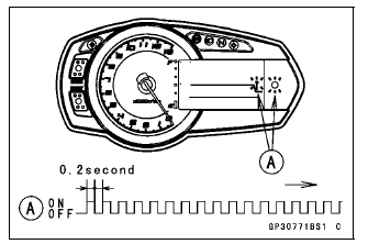
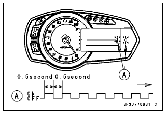
- The warning indicator light (LED) and the immobilizer warning symbol [A] blink 1 time and stop for 1 second and then repeat this cycle.
- Turn to OFF the ignition switch and remove the registered ignition key.
- The immobilizer warning symbol [B] disappears.
- The warning indicator light (LED) [A] then blinks for 15 seconds; it means the ECU is in the registration mode.
- After 15 seconds, the ECU ends the registration mode and stops blinking the warning indicator light (LED).
NOTE
- Insert and turn on the next key between 15 seconds that the ECU is in the registration mode.
- When a registration mode was ended, do the registered ignition key verification procedure over again to restart it. This applies to all ignition key registration.
- Insert the other remaining registered ignition key into the ignition switch, and turn it to ON.
NOTE
- Keep other ignition keys away from the immobilizer antenna.
- If there is any problem in the registration, the warning indicator light (LED) and the immobilizer warning symbol [A] blink to display the collation error.
Immobilizer Amplifier Failure
When Registered Ignition Key is Inserted.

Ignition Key Collation Error
- The other remaining ignition key is registered in the ECU.
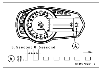
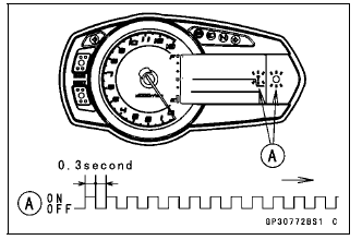
- The warning indicator light (LED) and the immobilizer warning symbol [A] blink 2 times and stop for 1 second and then repeat this cycle.
- Turn to OFF the ignition switch and remove the other remaining ignition
key.
- The immobilizer warning symbol [B] disappears.
- The warning indicator light (LED) [A] then blinks for 15 seconds.
- After 15 seconds, the ECU ends the registration mode and stops blinking the warning indicator light (LED).
NOTE
- This procedure registered the registered ignition key and one ignition key.
If more keys registration is needed, go to next procedures within the registration mode.
- Insert the ignition key 1 into the ignition switch, and turn it to ON.
- If there is any problem in the registration, the warning indicator
light (LED) and the immobilizer warning symbol [A] blink to display the
collation error code.
Immobilizer Amplifier Failure
- If there is any problem in the registration, the warning indicator
light (LED) and the immobilizer warning symbol [A] blink to display the
collation error code.
When Registered Ignition Key is Inserted.
Ignition Key Collation Error
- The ignition key 1 is successfully registered in the ECU.
- The warning indicator light (LED) and the immobilizer warning symbol [A] blink 3 times and stop for 1 second and then repeat this cycle.
- This procedure has registered the registered ignition key and 2 ignition keys.
- Turn to OFF the ignition switch and wait for period of more than 15 seconds.
- The registration mode automatically ends.
- The warning indicator light (LED) [A] goes off.
NOTE
- Turn the ignition switch to ON with the registered ignition key.
- Check that the engine can be started using all registered ignition keys.
Case 4: When all registered ignition keys are faulty or lost.
The all registered ignition keys replacement is considered very rare case. However if it is required, the following is necessary.
NOTE
- The ECU must be replaced with a new one because the registered ignition key code that is registered in the current ECU can not be rewritten.
- Prepare a new ECU [A] and 2 new ignition keys [B].
NOTE
- The key registration unit is not required.
- The key registration process is same as the case 3.
- Insert the first ignition key into the ignition switch and turn it ON.
- If there is any problem in the registration, the warning indicator
light (LED) and the immobilizer warning symbol [A] blink to display the
collation error.
Immobilizer Amplifier Failure
- If there is any problem in the registration, the warning indicator
light (LED) and the immobilizer warning symbol [A] blink to display the
collation error.
Ignition Key Collation Error

- The first ignition key is successfully registered in the ECU.
- The warning indicator light (LED) and the immobilizer warning symbol [A] blink 1 time and stops for 1 second and the repeats this cycle to indicate successful registration of the first ignition key.

- Turn to OFF the ignition switch and remove the first ignition key.
- The immobilizer warning symbol [B] disappears.
- The warning indicator light (LED) [A] then blinks for 15 seconds; it means the ECU is in the registration mode.
- After 15 seconds, the ECU ends the registration mode and stops blinking the warning indicator light (LED).
NOTE
- Insert and turn on the next key between 15 seconds that the ECU is in the registration mode.
- When a registration mode was ended, do the registered ignition key verification procedure over again to restart it. This applies to all ignition key registration.
- Insert the second ignition key into the ignition switch, and turn it to ON.
NOTE
- Keep other ignition keys away from the immobilizer antenna.
- If there is any problem in the registration, the warning indicator light (LED) and the immobilizer warning symbol [A] blink to display the collation error.
Immobilizer Amplifier Failure
When Registered Ignition Key is Inserted.
Ignition Key Collation Error
- The second ignition key is registered in the ECU.
- The warning indicator light (LED) and the immobilizer warning symbol [A] blinks 2 time and stops for 1 second and the repeats this cycle to indicate successful registration of the second ignition key.
- Turn to OFF the ignition switch and wait for period more than 15 seconds.
- The registration mode automatically ends.
- The warning indicator light (LED) [A] goes off.
NOTE
- Turn the ignition switch ON with the registered ignition key.
- Check that the engine can be started using all registered ignition keys.
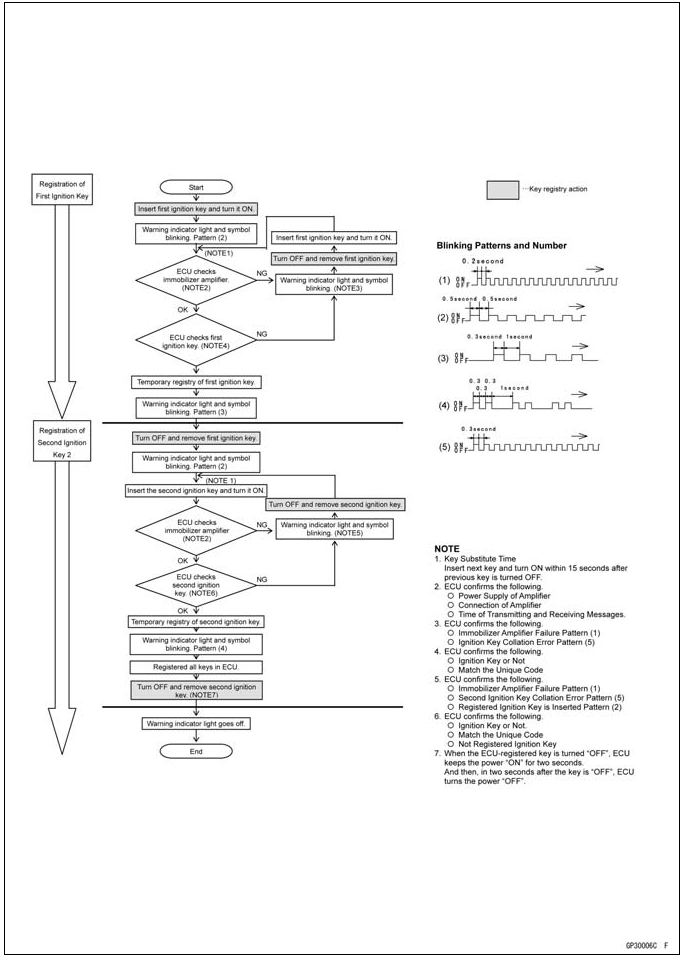
All Keys Initial Registration Flow Chart
Immobilizer System Parts Replacement
Ignition Switch (Immobilizer Antenna) Replacement
- Remove:
Fuel Tank (see Fuel Tank Removal in the Fuel System (DFI) chapter)
Handlebar Holder (see Handlebar Removal in the Steering chapter)
Left Lower Fairing (see Lower Fairing Removal in the Frame chapter) - Disconnect the lead connectors [A].
- Remove the steering stem (see Stem, Stem Bearing Removal in the Steering chapter).
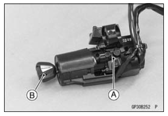
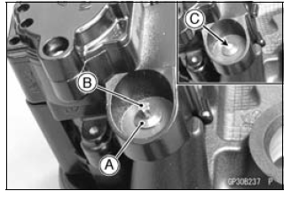
- Using a small chisel or punch [A], turn out the Torx bolts.
- Remove the ignition switch [B].
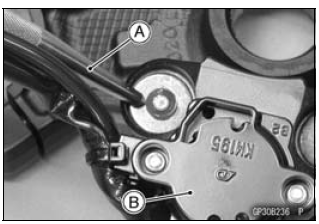
- Tighten a new Torx bolt [A] until the bolt head [B] is broken [C].
- Run the leads correctly (see Cable, Wire, and Hose Routing section in the Appendix chapter).
Immobilizer Amplifier Replacement
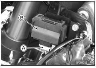
- Remove:
Left Center Fairing (see Center Fairing Removal in the Frame chapter)
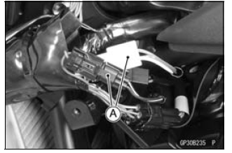
Immobilizer Amplifier connector [A]
Immobilizer Amplifier [B]
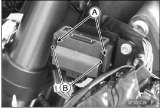
- Fit the slits [A] on the damper to the bracket projections [B].
ECU (Electronic Control Unit) Replacement (for Immobilizer Models)
NOTICE Never drop the ECU, especially on a hard surface.
Such a shock to the ECU can damage it.
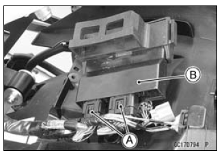
- Remove:
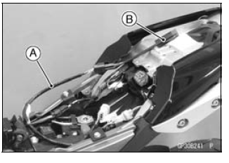
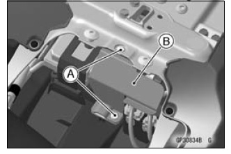
Front Seat (see Front Seat Removal in the Frame chapter) - Using a small chisel or other suitable tool, remove the screws [A] and ECU guard [B].
- Remove:
Relay Box (see Relay Box Removal)
ECU Connectors [A]
ECU [B]
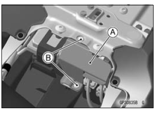
- Connect the connectors to the ECU.
- Install the ECU guard [A].
NOTICE Do not pinch the leads.
- Tighten the new screws [B] using the Kawasaki genuine screws of which threads are coated with locking agent.
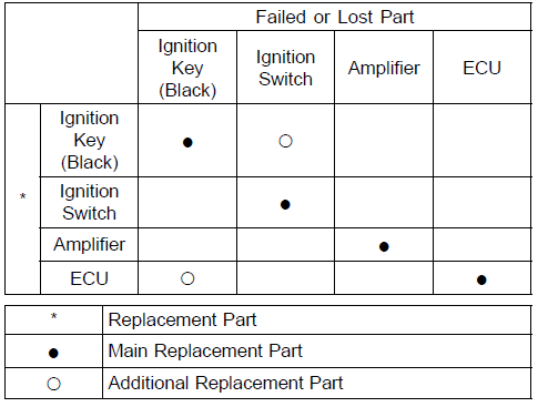
Immobilizer Relational Parts Replacement Chart
Immobilizer System Inspection
- Refer to the Immobilizer Amplifier and Blank Key Detection section in the Fuel System (DFI) chapter.
Immobilizer System Circuit
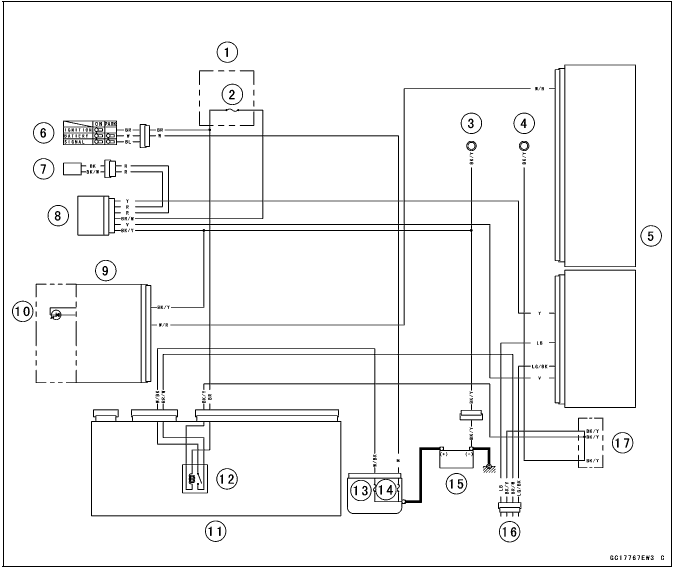
- Fuse Box 2
- Ignition Fuse 15 A
- Meter Ground
- Frame Ground
- ECU
- Ignition Switch
- Immobilizer Antenna
- Immobilizer Amplifier
- Meter Unit
- Water Temperature/Oil Pressure/FI/Immobilizer Warning Indicator Light (LED)
- Relay Box
- ECU Main Relay
- FI Fuse 15 A
- Main Fuse 30 A
- Battery 12 V 8 Ah
- Immobilizer/Kawasaki Diagnostic System Connector
- Water-proof Joint C
See also:
 Kawasaki Z1000SX - Service manual > Meter, Gauge, Indicator Unit
Electronic Combination Meter Unit Inspection Remove the meter unit [A]. [1] Neutral Indicator Light (LED) Ground (-) [2] Right Turn Signal indicator Light (LED) (+) [3] High Beam Indicator Light (LED) (+) [4] Water Temperature Sensor [5] Unused [6] Unused [7] Unused [8] Unused [9] Unused [10] Left Turn Signal indicator Light (LED) (+) [11] Warning Indicator Light (LED) (-) [12] Tachometer Pulse [13] Speed Sensor Pulse [14] ECU Communication Pulse [15] Fuel Level Sensor [16] Ignition [17] Battery (+) [18] Unused [19] Ground (-) [20] ABS Indicator Light (LED) (-) (Equipped Models)
Kawasaki Z1000SX - Service manual > Switches and Sensors
Brake Light Timing Inspection Refer to the Brake Light Switch Operation Inspection in the Periodic Maintenance chapter. Brake Light Timing Adjustment Refer to the Brake Light Switch Operation Inspection in the Periodic Maintenance chapter.
 Rider's Manual BMW R 1250 GS GSA
 Owner's Manual Harley-Davidson Sportster XL1200X Forty-Eight
 Owner's Manual Honda CBR650R
 Service manual Honda CBR650
 Owner's Manual Honda PCX125
 Owner's Manual Kawasaki Z1000SX
 Service manual Kawasaki Z1000SX
 Owner's Manual Lexmoto Echo
 Owner's Manual Royal Enfield Interceptor 650
 Service manual Royal Enfield Interceptor 650
 Owner's Manual Yamaha MT-07