 Kawasaki Z1000SX - Service manual > Meter, Gauge, Indicator Unit
Electronic Combination Meter Unit Inspection
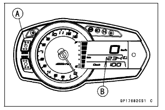
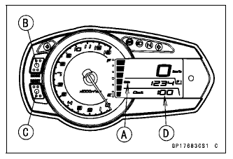
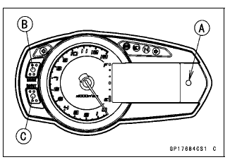
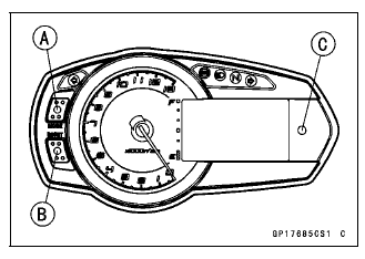
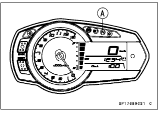
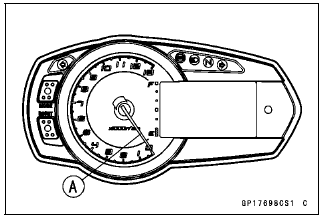
- Remove the meter unit [A].
[1] Neutral Indicator Light (LED) Ground (-)
[2] Right Turn Signal indicator Light (LED) (+)
[3] High Beam Indicator Light (LED) (+)
[4] Water Temperature Sensor
[5] Unused
[6] Unused
[7] Unused
[8] Unused
[9] Unused
[10] Left Turn Signal indicator Light (LED) (+)
[11] Warning Indicator Light (LED) (-)
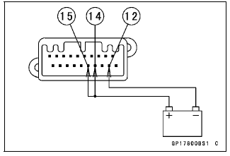
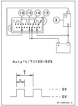
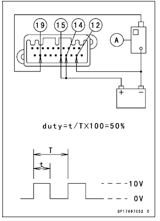
[12] Tachometer Pulse
[13] Speed Sensor Pulse
[14] ECU Communication Pulse
[15] Fuel Level Sensor
[16] Ignition
[17] Battery (+)
[18] Unused
[19] Ground (-)
[20] ABS Indicator Light (LED) (-) (Equipped Models)
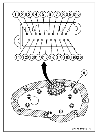
NOTICE Do not drop the meter unit. Place the meter unit so that it faces upward. If the meter unit is left upside down or sideways for a long time or dropped, it will malfunction. Do not short each terminals.
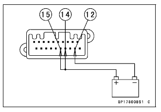
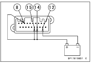
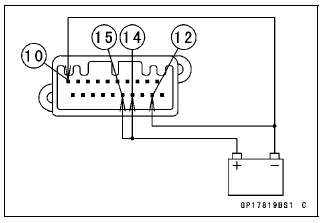
Check 1: Meter Unit Primary Operation Check
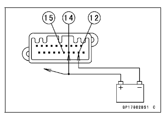
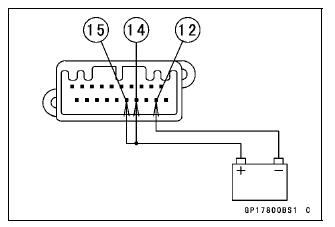
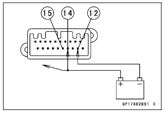
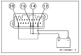
- Using the auxiliary leads, the 12 V battery [A] to the meter unit
connector as follows.
- Connect the battery positive (+) terminal to the terminal [14].
- Connect the battery negative (-) terminal to the terminal [12].
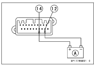
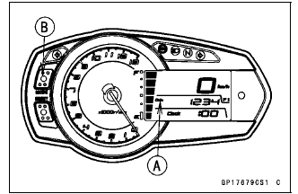
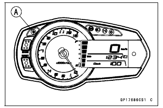
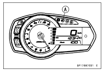
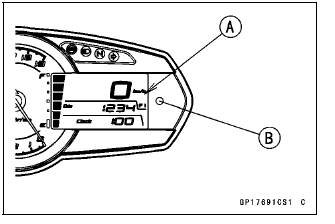
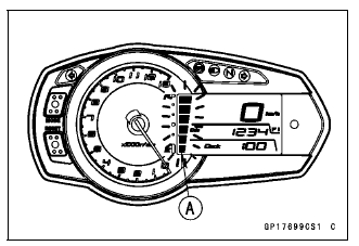
- Check that the tachometer needle [A] momentarily points their last
readings and back to the minimum position.
If the meter unit does not work, replace the meter assembly.
- Connect the terminal [15] to the battery (+) terminal.
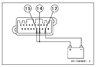
- Check the following items.
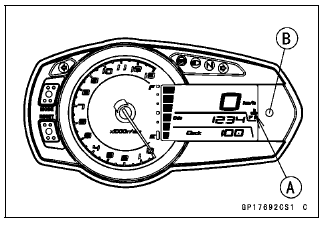
- The tachometer needle momentarily points their last readings and back to the minimum position.
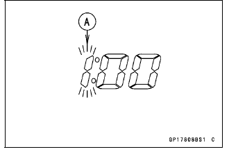
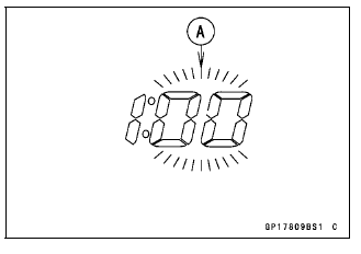
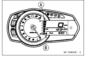
- All the LCD (Liquid Crystal Display) segments [A] and warning indicator light (LED) [B] blink 1 time, then appear for about 1 second.
- After the following LCD (Liquid Crystal Display) will display the action (1, 2) within about 2 seconds.
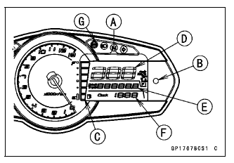
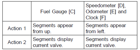
- The all segments of the fuel gauge in the display will flash.
(This function is Fuel Level Sensor Line Self-Diagnosis Mode. Refer to Fuel Level Sensor Line Self-Diagnosis Mode Inspection.)
- The ABS indicator light (LED) [G] goes on. (Equipped Models)
If the meter unit does not work, replace the meter assembly.
NOTE
- Currently, the wiring that relates to flashing has been disconnected
for the meter is removed from main harness.
Therefore, the above flash has occurred.
- Disconnect the terminal [15].
- All the LCD segments and LED warning indicator lights disappear.
If the meter unit does not work, replace the meter assembly.
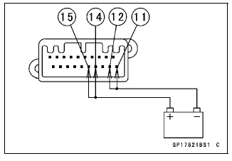
Check 2: Meter Communication Line (Service Code 39) Check
- Connect the leads in the same circuit as Check 1.
- Wait 10 seconds and the FI in the display and warning indicator light (LED) flash.
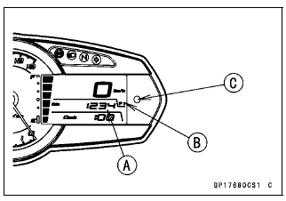
- Set the ODO mode [A] by pushing the MODE button [B].
- Push the MODE button for more than 2 seconds.
- Check the following items.
- The number 39 [A] and FI [B] in the display appear and flash.
- The warning indicator light (LED) [C] flashes.
- Push the MODE button for more than 2 seconds.
- Check the following items.
- The display returns ODO mode from number 39.
- The FI in the display and warning indicator light (LED) flash.
If the meter unit does not work, replace the meter assembly.
NOTE
- The number 39 is service code of Self-Diagnosis (see Fuel System chapter). It is the service code of the meter communication line error.
- The number 39 and FI in the display disappear when the meter unit is connected to main harness of the normal motorcycle.
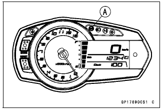
Check 3: MODE Button Operation Check
- Connect the leads in the same circuit as Check 1.
- By pushing the MODE button [A] each time, check that the display [B] changes as follows.
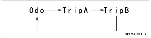
If the display function does not work, replace the meter assembly.
Check 4: Clock Setting Check
- Connect the leads in the same circuit as Check 1.
- Set the ODO mode [A] by pushing the MODE button [B].
- Push the RESET button [C] for more than two seconds.
- The clock setting menu (hour and minute) [D] should flash.
- Push the RESET button.
- The hour display [A] starts flashing.
- By pushing the MODE button each time, check that the hour display changes.
- By pushing the RESET button, check that the hour display decides and minute display [A] starts flashing.
- By pushing the MODE button each time, check that the minute display changes.
- By pushing the RESET button, check that the hour and minute display start flashing.
- By pushing the MODE button, check that the hour and minute display decide.
- When both hour and minute display is flashing, by pushing the RESET button, check that the hour display start flashing. This flashing returns the hour setting display.
If the display function does not work, replace the meter assembly.
- If the terminal 15 disconnected when the clock is setting, clock is set at time of that time.
Check 5: Immobilizer Flashing Mode Inspection (Equipped Models)
- Connect the leads in the same circuit as Check 1.
- Disconnect the terminal [15].
- Check that the warning indicator light (LED) [A] starts flashing (Immobilizer Warning Indicator Light Flashing Mode).
- Push the MODE [B] and RESET [C] buttons more than 2 second, within 20 seconds after the terminal [15] disconnected.
- Check that the warning indicator light (LED) goes on one second, and then the light goes off (Immobilizer Warning Indicator Light No Flashing Mode).
NOTE
- For this inspection, be sure the battery is 12.2 V or more. Immobilizer Warning Indicator Light Flashing Mode does not work, when the battery voltage is less than 12 +-0.2 V.
- Connect the terminal [15] to the battery (+) terminal.
- And then, disconnect the terminal [15].
- Push the MODE [A] and RESET [B] buttons more than 2 second, within 20 seconds after the terminal [15] disconnected.
- Check that the warning indicator light (LED) [C] goes on one second, and
then the light starts flashing (Immobilizer Warning Indicator Light Flashing
Mode).
If the meter function does not work, replace the meter assembly.
Check 6: Left Turn Signal Indicator Light (LED) Inspection
- Connect the leads in the same circuit as Check 1.
- Connect the terminal [1] to the battery (+) terminal.
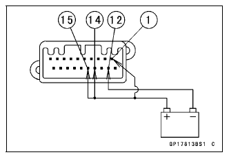
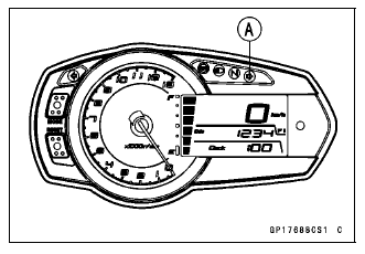
- Check that the left turn signal indicator light (LED) [A] goes on.
If the indicator light (LED) does not go on, replace the meter assembly.
Check 7: High Beam Indicator Light (LED) Inspection
- Connect the leads in the same circuit as Check 1.
- Connect the terminal [8] to the battery (+) terminal.
- Check that the high beam indicator light (LED) [A] goes on.
If the indicator light (LED) does not go on, replace the meter assembly.
Check 8: Right Turn Signal Indicator Light (LED) Inspection
- Connect the leads in the same circuit as Check 1.
- Connect the terminal [9] to the battery (+) terminal.
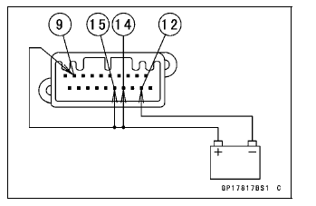
- Check that the right turn signal indicator light (LED) [A] goes on.
If the indicator light (LED) does not go on, replace the meter assembly.
Check 9: Neutral Indicator Light (LED) Inspection
- Connect the leads in the same circuit as Check 1.
- Connect the terminal [10] to the battery (-) terminal.
- Check that the neutral indicator light (LED) [A] goes on.
If the indicator light (LED) does not go on, replace the meter assembly.
Check 10: ABS Indicator Light (LED) Inspection (Equipped Models)
- Connect the leads in the same circuit as Check 1.
- The ABS indicator light (LED) goes on.
- Connect the terminal [11] to the battery (-) terminal.
- Check that the ABS indicator light (LED) [A] goes off.
If the indicator light (LED) does not go off, replace the meter assembly.
Check 11: Oil Pressure Warning Indicator Light (LED) Inspection
- Connect the leads in the same circuit as Check 1.
- Connect the terminal [20] to the battery (-) terminal.
- Check that the oil symbol [A] and oil pressure warning indicator light
(LED) [B] flash.
If the oil symbol and indicator light (LED) do not flash, replace the meter assembly.
Check 12: Water Temperature Warning Indicator Light (LED)
- Connect the leads in the same circuit as Check 1.
- The "- -" indication in the display of the water temperature meter appears.
- Connect the terminal [7] to the battery (-) terminal.

- Check that the water temperature symbol [A] and water temperature
warning indicator light (LED) [B] flash.
If the water temperature symbol and indicator light (LED) do not flash, replace the meter assembly.
Check 13: Fuel Gauge Inspection
- Connect the leads in the same circuit as Check 1.
- The all segments of the fuel gauge in the display will flash.
- Connect the variable rheostat [A] to the terminal [16] and the battery (-) terminal.
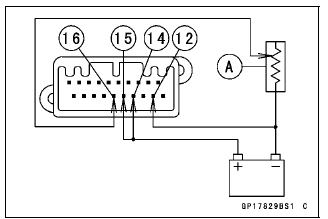
- Check that the segments number of the fuel level gauge [A] matches the
resistance value of the variable rheostat.
- When the terminal [16] is connected, one segment in the fuel level gauge should appear about every 15 seconds.
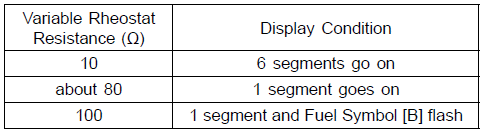
If the display function does not work, replace the meter assembly.
Check 14: Speedometer Inspection
- Connect the leads in the same circuit as Check 1.
- The speed equivalent to the input frequency is indicated in the
oscillator [A], if the square wave is input into terminal [18].
- Indicates approximately 60 km/h if the input frequency is approximately 189 Hz.
- Indicates approximately 60 mph if the input frequency is approximately 303 Hz.
If the meter function does not work, replace the meter assembly.
NOTE
- The input frequency of the oscillator adds the integrated value of the odometer.
- The integrated value of the odometer cannot be reset.
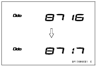
Check 15: Odometer Check
- Check the odometer with the speedometer check in the same way.
If value indicated in the odometer is not added, replace the meter unit.
NOTE
- The data is maintained even if the battery is disconnected.
- When the figures come to 999999, they are stopped and locked.
Check 16: Trip A/B Meter Check
- Check the trip meter with the speedometer in the same way.
If value indicated in the trip meter is not added, replace the meter unit.
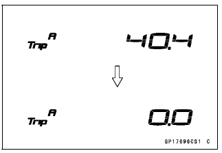
- Check that when the RESET button is pushed for more than two seconds,
the figure display turns to 0.0.
If the figure display does not indicate 0.0, replace the meter unit.
Check 17: Tachometer Inspection
- Connect the leads in the same circuit as Check 1.
- The engine speed (rpm) equivalent to the input frequency is indicated in
the oscillator [A], if the square wave is input into terminal [19].
- Indicates approximately 4 000 rpm if the input frequency is approximately 133.3 Hz.
If the meter function does not work, replace the meter assembly.
- Disconnect the terminal [15].
- Check that the tachometer needle [A] back to the minimum (0) position.
If the meter unit does not work, replace the meter assembly.
Fuel Level Sensor Line Self-Diagnosis Mode Inspection
NOTE
- Usually when the open or short of the fuel level sensor circuit is detected, it becomes the Fuel Level Sensor Line Self-Diagnosis Mode.
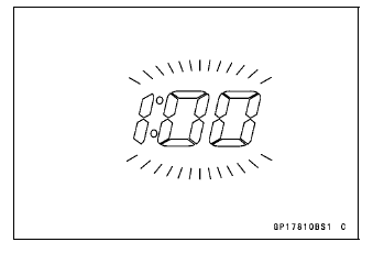
- The all segments of the fuel gauge [A] in the display will flash. (This function is Fuel Level Sensor Line Self-Diagnosis Mode.)
If the meter enters the self-diagnostic mode when the meter is installed in the motorcycle, check the fuel level sensor (see Fuel Level Sensor Inspection) and wiring.
If the fuel level sensor and wiring are good, replace the meter assembly.
Meter Circuit
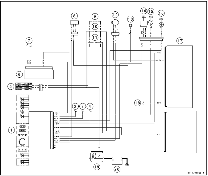
- Meter Unit
- to Turn Signal Switch (Right)
- to Turn Signal Switch (Left)
- to Dimmer Switch and Passing Button (Equipped Models)
- Ignition Switch
- ABS Hydrauric Unit (Equipped Models)
- to France Ground
- Fuel Level Gauge
- Fuse Box 2
- Meter Fuse 10 A
- Ignition Fuse 15 A
- Speed Sensor
- Meter Ground
- Water Temperature Sensor
- Neutral Switch
- Oil Pressure Switch
- ECU
- to Frame Ground
- Main Fuse 30 A
- Battery 12 V 8 Ah
See also:
 Kawasaki Z1000SX - Service manual > Radiator Fan System
Fan Motor Inspection Remove the left lower fairing (see lower Fairing Removal in the Frame chapter). Remove the rubber band [A]. Slide the dust cover [A]. Disconnect the connector [B]. Using an auxiliary leads, supply battery power to the fan motor.
Kawasaki Z1000SX - Service manual > Immobilizer System (Equipped Models)
This motorcycle is equipped with an immobilizer system to protect the motorcycle from theft. This system provides a theft proof device by means of matching a code between the inbuilt key transponder and ECU (Electronic Control Unit). If the code does not match, ignition system, injectors, subthrottle valve actuator and exhaust butterfly valve actuator will not operate and the engine will not start.
 Rider's Manual BMW R 1250 GS GSA
 Owner's Manual Harley-Davidson Sportster XL1200X Forty-Eight
 Owner's Manual Honda CBR650R
 Service manual Honda CBR650
 Owner's Manual Honda PCX125
 Owner's Manual Kawasaki Z1000SX
 Service manual Kawasaki Z1000SX
 Owner's Manual Lexmoto Echo
 Owner's Manual Royal Enfield Interceptor 650
 Service manual Royal Enfield Interceptor 650
 Owner's Manual Yamaha MT-07