 Royal Enfield Interceptor 650 - Service manual > Air Filter Box Assembly
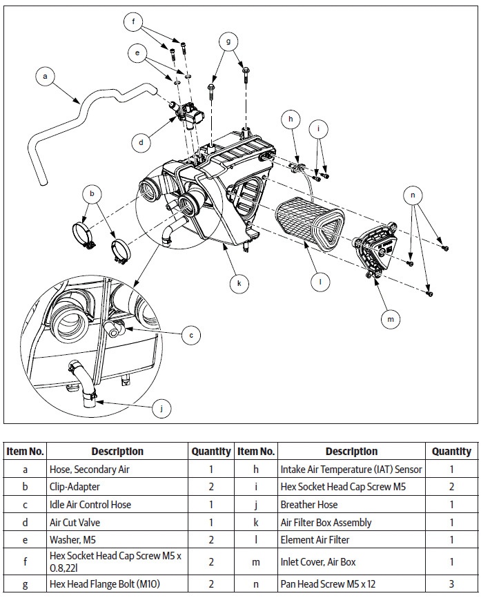
Dismantling
Air Filter Element
CAUTION Ensure the motorcycle is upright on a firm and flat surface.
- Ensure ignition switch and engine stop switch are in OFF position.
- Remove the following parts:
- Side panel RH.
- Rider seat.
- Side panel LH.
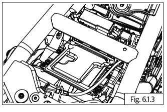
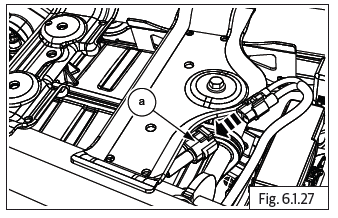
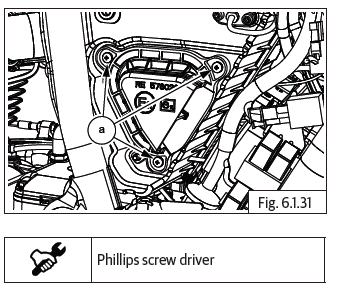
- Gently support air filter element cover and loosen and remove 3 Nos. pan head screws (a) from air filter box assembly.
NOTE
- DO NOT tap or apply excessive force on the screws.
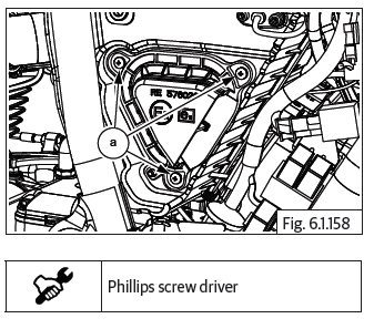
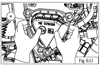
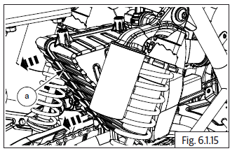
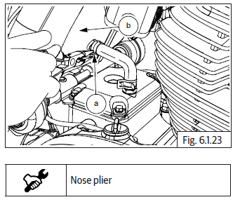
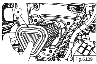
- Remove air filter element cover (a) from air filter box assembly.
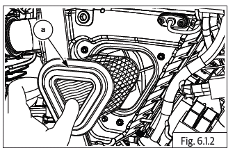
- Gently pull out air filter element (a) from air filter box assembly.
Air Filter Box Assembly
- Ensure ignition switch and engine stop switch are in OFF position.
- Remove the following parts:
- Side panel RH.
- Rider seat.
- Side panel LH.
- Fuel tank dismantling.
CAUTION Ensure the following: Fuel feed and return hose is disconnected from the fuel rail.
Fuel is drained completely from fuel feed hose.
Disconnect the EVAP and drain hoses.
Wiring couplers to fuel pump and low fuel sensor are disconnected.
WARNING Gasoline is extremely flammable and highly explosive. Improper handling can lead to fatal accident or serious injury.
- Remove utility box from frame RH. Refer electrical system.
- Disconnect Battery terminals and remove battery.
- Remove Battery tray.
- Disconnect ECU wiring coupler and remove ECU.
CAUTION Ensure the locks are fully lifted up and released, before disconnecting wiring connectors from the ECU. Ensure the locks are handled with care and do not get damaged or broken.
Damaged or broken locks will result in loose connections and cause the ECU to fail.
- Remove the following parts:
- Rear wheel assembly.
- Rear mudguard infill cover.
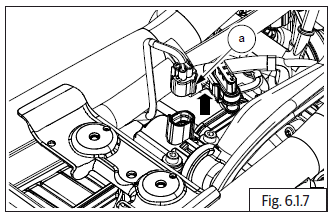
- Disconnect intake air temperature sensor wiring coupler (a).
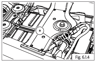
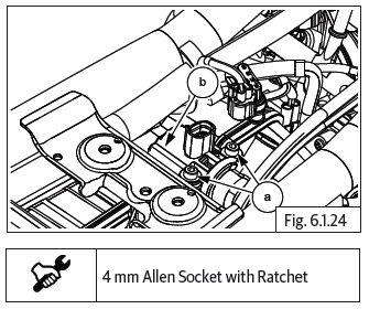
- Support intake air temperature (IAT) sensor, loosen and remove 2 Nos. Hex socket head bolts (M5) (a) holding intake air temperature (IAT) sensor to air filter box assembly on the LH side.
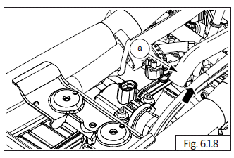
- Gently pull out intake air temperature sensor (a) from air filter box assembly.
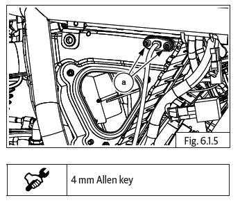
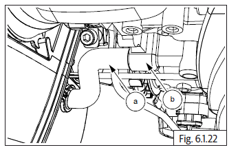
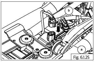
- Disconnect air cut valve (ACV) wiring connector (a).
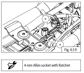
- Gently pull out and remove hose (a), secondary air from air cut valve.
- Support air cut valve, loosen and remove 2 Nos. Hex socket head cap screws (M5) (a) holding air cut valve to air filter box assembly on the top RH side.
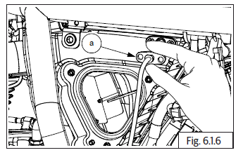
- Gently pull out air cut valve (b) from air filter box assembly.
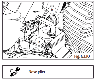
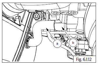
- Release clip (a) and disconnect breather hose (b) from air filter box assembly.
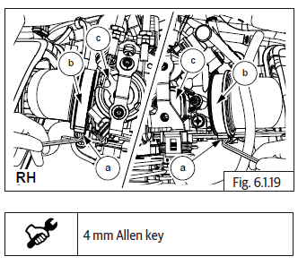
- Loosen 2 Nos. Hex socket screws (M5) (a) sufficiently on the worm clips (b) on the LH and RH bellows between throttle body (c) and air filter box assembly.
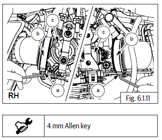
- Disconnect idle air control (IAC) hose (a) from throttle body (b).
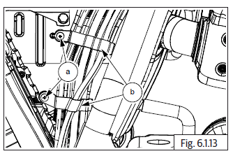
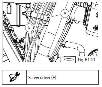
- Loosen and remove 2 Nos. pan head screws (a) on air filter box assembly RH side and remove clamps (b) provided for routing of the brake hoses and wiring harness.
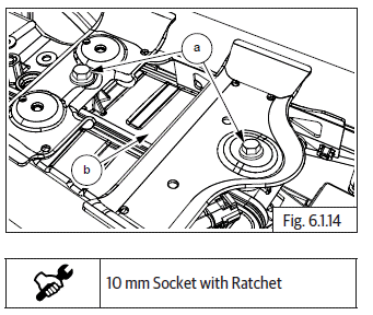
- Loosen and remove 2 Nos. Hex flange head bolts (M6) (a) from frame above air filter box assembly top (b).
- Ensure worm clips on inlet bellows are sufficiently loose and bellows are not stuck on throttle body.
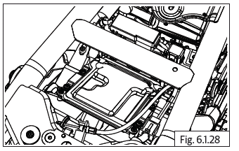
- Gently remove air filter box assembly (a) from frame by pulling to the rear to release the bellows from the throttle body.
Inspection
- Inspect air filter box assembly for any damages or cracks.
- Inspect air intake bellows for any damages, cracks and/or brittleness of the bellows.
- Inspect rubber seals, hoses for cuts, cracks or damages. Replace seals and rubber parts whenever they are removed.
- Inspect air filter element carefully for any deformation, damages, heavy clogging with dirt, soggy condition, and/or foreign particles embedded in the element. Replace if any of these conditions are observed.
Clean
- Clean air filter element (a) after first 500 Kms (300 Miles) and later based on the peroidic maintenance schedule OR more frequently if motorcycle is used in dusty/off-road conditions.
- Gently tap filter element with minimum force to dislodge heavy/embedded dust particles.
- Using low pressure compressed air, blow air from out side to inner side to remove fine dust particles.
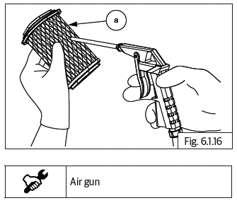
CAUTION DO NOT wash the element in water, gasoline or any solvents.
- Clean the air filter housing internals, with a soft damp cloth to remove dust.
Replace
- Replace all O-rings, rubber beadings, seals, gaskets, rubber parts etc., whenever air filter assembly is serviced.
- Replace air filter element every 20,000 Kms 12,000 Miles) or earlier if motorcycle is used in dusty/off road conditions.
Assembly
Air Filter Box Assembly
- Ensure worm clips on inlet bellows are sufficiently loose and correctly located in groove of bellows.
- Locate air filter box assembly (a) in frame from the rear, duly ensuring bellows are aligned correctly to throttle body.
- Locate bellows LH and RH on throttle body and ensure they are seated fully on throttle body.
- Align top mounting holes of air filter box assembly with mounting holes in frame.
- Tighten air filter box assembly (b) to frame using 2 Nos. Hex flange head bolts (M6) (a).
- Position worm clips correctly and tighten screws (M5) (a) on LH and RH bellows (b) firmly such that clips do not rotate and bellows are tight on throttle body (c).
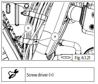
- Position upper clamp (a) correctly against air filter box assembly on RH side, duly ensuring mounting holes are aligned. Ensure the brake hoses and EVAP hose are correctly located inside clamp.
- Locate screw (b) on mounting hole of clamp and tighten clamp to air filter housing.
- Position lower clamp (a) correctly against air filter box assembly on RH side, duly ensuring mounting holes are aligned. Ensure brake hoses and wiring harness are correctly located inside clamp.
- Locate screw (b) on mounting hole of clamp and tighten clamp to air filter housing.
- Connect idle air control (IAC) hose (a) from air filter box assembly into throttle body (b).
- Ensure hose clip (a) is located on breather hose and connect breather hose to air filter box assembly (b).
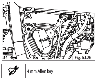
- Position air cut valve (b) into air filter box assembly top correctly and tighten with 2 Nos. Hex socket head bolts (M5) (a).
- Connect hose (a), secondary air to spout in air cut valve and ensure proper seating.
- Connect wiring coupler (b) to air cut valve.
- Position IAT sensor into air filter box assembly LH side correctly and tighten with 2 Nos. Hex socket head bolts (M5) (a).
- Connect wiring coupler to IAT sensor (a).
- Assemble the following parts:
- Assemble Battery tray and Battery.
- Rear mudguard infill cover.
- Rear wheel assembly.
- Locate ECU on frame and tighten with screws.
- Connect ECU wiring coupler from harness to ECU.
- Connect the Battery terminals.
- Locate utility box on frame RH and tighten in place.
- Assemble fuel tank assembly.
WARNING Gasoline is extremely flammable and highly explosive. Improper handling can lead to fatal accident or serious injury.
CAUTION Ensure the following: Wiring connectors to fuel pump and low fuel sensor are connected. EVAP and drain hoses are connected.
Fuel feed and return hose are connected to fuel rail.
Air Filter Element
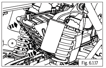
- The filter element (a) has one end open and the other end closed. Insert closed end of filter element into air filter box assembly correctly such that open end is facing outside.
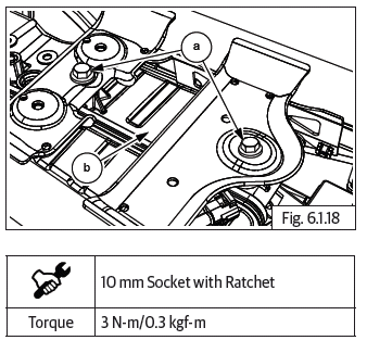
- Locate element cover (a) on air filter box assembly duly ensuring the locating hole (b) in cover is aligned to peg (c) in air filter box assembly.
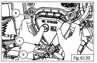
- Ensure proper seating of cover and tighten cover to air filter box assembly evenly and firmly with 3 Nos. Pan head screws (a).
CAUTION Do not over tighten the screws or use excessive force as it will damage the cover and the air filter box assembly.
- Assemble side panel LH
- Assemble rider seat
- Assemble side panel RH
Troubleshooting
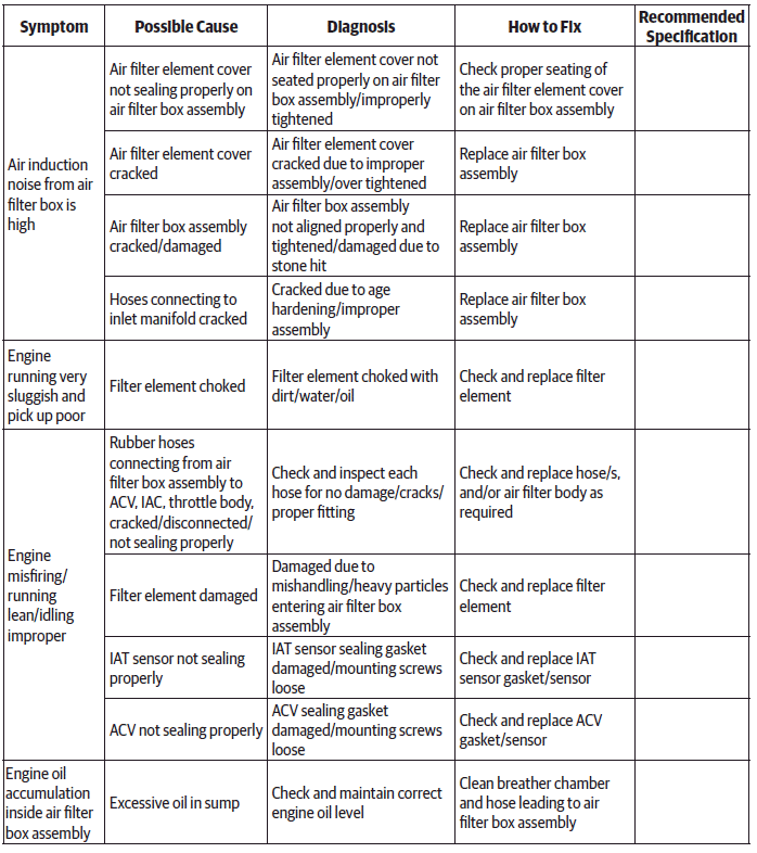
NOTE
- The trouble shooting given in this section is only related to issues with air filter. For complaints like sluggish running/misfiring improper idling etc., it will also be necessary to check the other aspects such as fuel, ignition, EMS, battery conditions etc., and correct.
See also:
 Royal Enfield Interceptor 650 - Service manual > Control Cables
Clutch Cable Dismantling Clutch Cable
 Rider's Manual BMW R 1250 GS GSA
 Owner's Manual Harley-Davidson Sportster XL1200X Forty-Eight
 Owner's Manual Honda CBR650R
 Service manual Honda CBR650
 Owner's Manual Honda PCX125
 Owner's Manual Kawasaki Z1000SX
 Service manual Kawasaki Z1000SX
 Owner's Manual Lexmoto Echo
 Owner's Manual Royal Enfield Interceptor 650
 Service manual Royal Enfield Interceptor 650
 Owner's Manual Yamaha MT-07