 Royal Enfield Interceptor 650 - Service manual > Control Cables
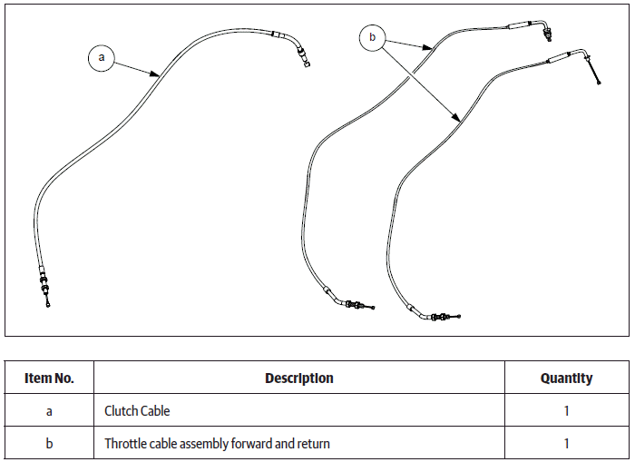
Clutch Cable
Dismantling
Clutch Cable
Cover RH End
CAUTION Ensure the motorcycle is upright on a firm and flat surface.
- Ensure ignition switch and engine stop switch are in OFF position.
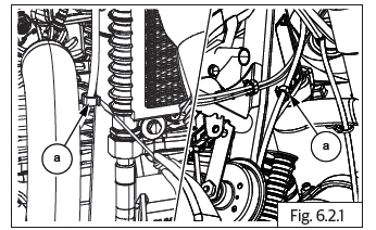
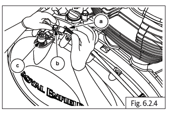
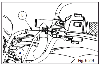
- Gently compress and release 2 clips (a) holding clutch cable to frame near exhaust pipe RH.
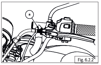
- Loosen lock nut and ensure adjuster (a) at the handlebar end is fully turned into the bracket LH to increase cable play.
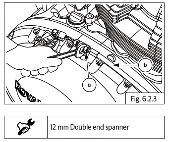
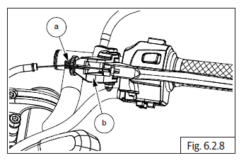
- Loosen outer locknut (M8) (a) completely on the clutch cable adjuster at RH cover end and push clutch cable (b) into cable guide in cover RH to increase the free play of the inner cable.
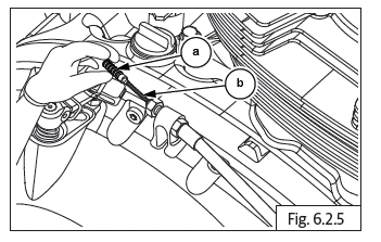
- Gently push inner cable (a) into clevis (b) in clutch shaft (c) and remove cable through the slot in the clevis.
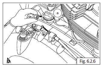
- Remove protective rubber boot (a) from clutch cable (b).
- Loosen adjuster nut (a) completely from the clutch cable and remove.
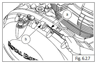
- Gently pull out clutch cable assembly (a) from the cable guide (b) in cover RH assembly.
Handlebar End
- Ensure the slot in the adjuster (a) and locknut are aligned with the slot in the clutch bracket (b).
- Gently pull out the outer cable (a) from the adjuster. Rotate and align adjuster with slot in clutch bracket and release inner cable (b) from lever eyelet.
- Remove clutch cable from motorcycle.
NOTE
- Please ensure the securing clips holding clutch cable to frame are released before attempting to remove clutch cable from motorcycle.
See also:
 Royal Enfield Interceptor 650 - Service manual > Air Filter Box Assembly
Dismantling Air Filter Element
Royal Enfield Interceptor 650 - Service manual > Throttle Cable
Throttle Body End CAUTION Ensure the motorcycle is upright on a firm and flat surface. Ensure Ignition switch and Engine stop switch are in OFF position. Remove side panel RH. Remove rider seat. Loosen fuel tank assembly mountings and carefully slide and lift fuel tank up to access 2 clips holding the throttle cables to frame on RH side. Gently compress and release the clip (a) holding throttle cable to frame on the RH side. Loosen and remove 2 Nos. Hex socket screws (M5) (a) on throttle body cover RH (b) and remove cover. Loosen 2 Nos. Hex nuts (M6) (a) fully on top of throttle cable bracket (b) to increase inner cable (c) free play. Push cable adjusters fully into the bracket and loosen the 2 inner hex nuts (M6) on the throttle cable adjusters. Ensure both inner nuts are free from the adjusters and gently pull out the adjuster of the inside cable till it is out of the bracket and slide the inner cable out through the slot in the bracket. Repeat above process for the other throttle cable. Rotate inner cable (a) till it is aligned with the slot in the rotor (b) on throttle body and remove cable from the eyelet. Repeat above process for removing the other throttle cable. Remove the cables from the bracket on throttle body.
 Rider's Manual BMW R 1250 GS GSA
 Owner's Manual Harley-Davidson Sportster XL1200X Forty-Eight
 Owner's Manual Honda CBR650R
 Service manual Honda CBR650
 Owner's Manual Honda PCX125
 Owner's Manual Kawasaki Z1000SX
 Service manual Kawasaki Z1000SX
 Owner's Manual Lexmoto Echo
 Owner's Manual Royal Enfield Interceptor 650
 Service manual Royal Enfield Interceptor 650
 Owner's Manual Yamaha MT-07