 Royal Enfield Interceptor 650 - Service manual > Throttle Cable
Throttle Body End
CAUTION Ensure the motorcycle is upright on a firm and flat surface.
- Ensure Ignition switch and Engine stop switch are in OFF position.
- Remove side panel RH.
- Remove rider seat.
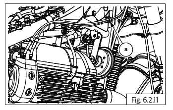
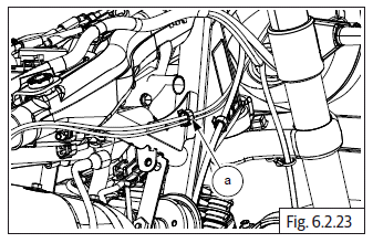
- Loosen fuel tank assembly mountings and carefully slide and lift fuel tank up to access 2 clips holding the throttle cables to frame on RH side.
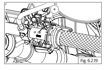
- Gently compress and release the clip (a) holding throttle cable to frame on the RH side.
- Loosen and remove 2 Nos. Hex socket screws (M5) (a) on throttle body cover RH (b) and remove cover.
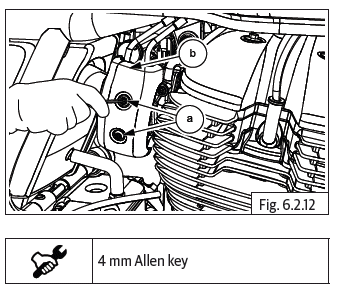
- Loosen 2 Nos. Hex nuts (M6) (a) fully on top of throttle cable bracket (b) to increase inner cable (c) free play.
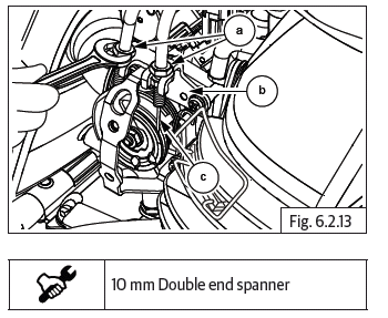
- Push cable adjusters fully into the bracket and loosen the 2 inner hex nuts (M6) on the throttle cable adjusters.
- Ensure both inner nuts are free from the adjusters and gently pull out the adjuster of the inside cable till it is out of the bracket and slide the inner cable out through the slot in the bracket.
- Repeat above process for the other throttle cable.
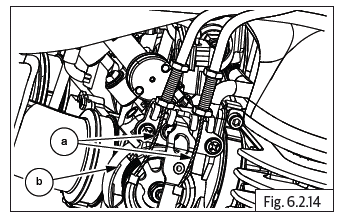
- Rotate inner cable (a) till it is aligned with the slot in the rotor (b) on throttle body and remove cable from the eyelet.
- Repeat above process for removing the other throttle cable.
- Remove the cables from the bracket on throttle body.
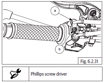
Handlebar End
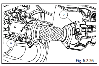
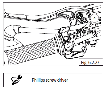
- Loosen screw (a) on the front cable and rotate the clip (b) holding throttle cable to throttle rotor housing.
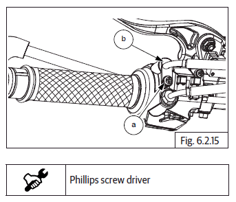
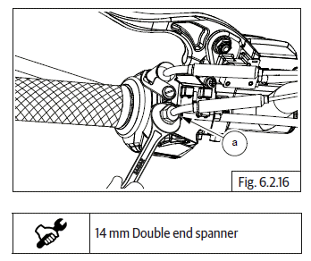
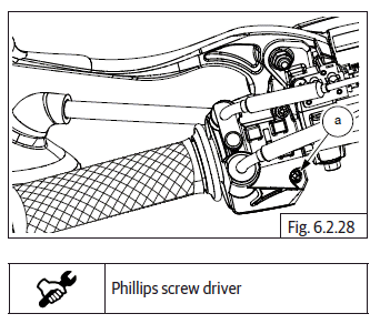
- Loosen the hex nut (M8) (a) holding rear cable to throttle rotor housing.
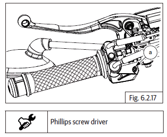
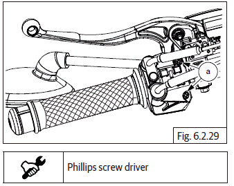
- Loosen and remove 2 Nos. Phillips head screws (a) from the bottom of the throttle rotor housing and separate the halves.
- Gently pull up the inner cable (a) from the slot in the throttle rotor (b), rotate and ensure it is aligned to the slot in the throttle rotor grip and remove.
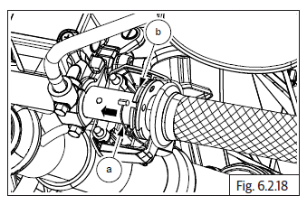
- Repeat the above process to remove the other inner cable (a).
- Gently remove the cables from the rotor housing bottom.
- Remove the twin cables from the motorcycle.
- Remove throttle rotor.
Inspection
Cables
- Clean and inspect inner cables top and bottom ends for frayed and/or broken strands.
- Clean and inspect outer cables for brittleness, damages and/or cracks.
- Inspect the cable adjuster threads and hex nuts for any wear out and/or damage.
- Check free movement of the inner cables in the outer cables and no stickiness.
- Replace control cables as per the recommendations in the maintenance chart.
CAUTION DO NOT wash control cables, especially inner cables, using any solvents since it will damage the protective layer inside the control cables.
Do not lubricate inner cable by spraying any lubricants into the outer cable.
Do not roll the cables into a tight wind for storing after removal. Store them as straight as possible to avoid damage to the inner layer/ cable.
Use a soft cloth with a mild cleaning agent if necessary, to wipe off the dirt, grease or grime on the outer cables.
Clutch Lever Bracket Adjusting Screw and Clutch Lever
- Inspect the cable seating area in the adjuster on clutch lever bracket for any damages/cracks.
- Inspect the threads of the adjuster and the clutch lever bracket for any damages, threads wear out.
Throttle Rotor, Grip and Housing on Handlebar RH
- Inspect throttle rotor grip for any damages and/or cracks.
- Inspect throttle rotor for any damages/wear out.
- Inspect cable seating eyelets in the throttle rotor for any damages, fraying etc.
- Inspect the throttle rotor movement slots in the top and bottom housing for any damages/wear out.
Assembly
Throttle Cable
- Route both the cables between the top yoke and frame head tube on the RH side under fuel tank.
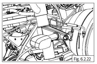
- Locate cable holding clips (a) on throttle cables and lock into the frame.
Handlebar End
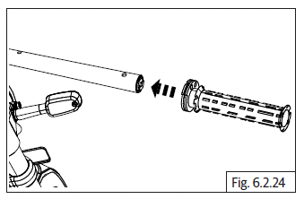
- Lubricate throttle rotor grip inside with general purpose grease and assemble on handlebar RH.
- Ensure the cable slots on the rotor are facing above for correct and ease of assembly of inner cables.
- Ensure the adjusters on both cables are set at their center for finer adjustments later.
- Insert throttle cable (a) with hex nut (b) into the rear hole of the throttle rotor housing and locate inner cable in the rear eyelet on the throttle rotor.
- Align inner cable to the slot in the rotor, rotate and ensure proper routing of the inner cable in the slot in throttle rotor.
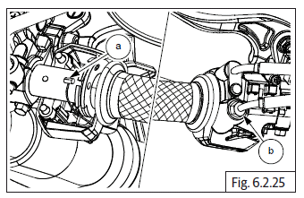
- Insert the other throttle cable (a) and clip (b) into the front hole in throttle rotor housing and locate inner cable in front eyelet on throttle rotor.
- Align inner cable to slot in the rotor, rotate and ensure proper routing of the inner cable in the slot in throttle rotor.
- Locate and hold bottom housing against handlebar such that the throttle rotor is correctly seated in the groove in the bottom housing.
- Rotate throttle rotor clockwise, till it is resting on the bottom housing.
- Locate the top housing on the handlebar above the rotor, duly ensuring
the following:
- Throttle rotor is correctly seated in the groove in the top housing.
- The locking peg in the top housing is located correctly into the hole in the handlebar.
- The seating faces of the housing are matched correctly.
- Support top and bottom housings, check for free movement of the throttle rotor by gently rotating the throttle rotor grip.
- Insert long Phillips head screw (a) into the front mounting hole in bottom housing and tighten just sufficiently.
- Insert short Phillips head screw (a) into rear mounting hole in bottom housing and tighten just sufficiently.
- Check and ensure rotor housing is locked properly in handlebar and free movement of throttle rotor and tighten both screws (a) evenly till the housing is tight on the handlebar.
- Locate Hex nut (M8) (a) of the rear cable into bottom housing and tighten.
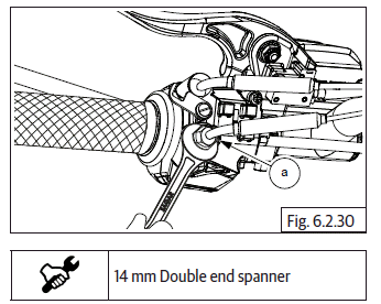
- Rotate clip (a) such that the groove is duly positioned on the cable and tighten locking screw (b).
See also:
 Royal Enfield Interceptor 650 - Service manual > Control Cables
Clutch Cable Dismantling Clutch Cable
Royal Enfield Interceptor 650 - Service manual > Throttle Body End
Gently open throttle at handlebar end and identify the cable in which the inner cable retracts. Insert this cable into the front slot in the bracket in the throttle body and ensure the adjuster is fully into the bracket on throttle body. Assemble lock nut on the inner cable. Position inner cable (a) to the front slot of the rotor on throttle body, insert inner cable into the eyelet and route the cable in the groove in the rotor of the throttle body. Repeat above steps to locate the other cable in the rear slot of the rotor on throttle body. Ensure both inner cables are seated properly in the eyelets at throttle body end and handlebar end. Gently rotate throttle rotor at handlebar and ensure they are operating properly.
 Rider's Manual BMW R 1250 GS GSA
 Owner's Manual Harley-Davidson Sportster XL1200X Forty-Eight
 Owner's Manual Honda CBR650R
 Service manual Honda CBR650
 Owner's Manual Honda PCX125
 Owner's Manual Kawasaki Z1000SX
 Service manual Kawasaki Z1000SX
 Owner's Manual Lexmoto Echo
 Owner's Manual Royal Enfield Interceptor 650
 Service manual Royal Enfield Interceptor 650
 Owner's Manual Yamaha MT-07