 Royal Enfield Interceptor 650 - Service manual > Throttle Body End
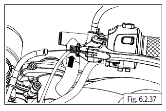
- Gently open throttle at handlebar end and identify the cable in which the inner cable retracts.
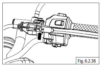
- Insert this cable into the front slot in the bracket in the throttle body and ensure the adjuster is fully into the bracket on throttle body.
- Assemble lock nut on the inner cable.
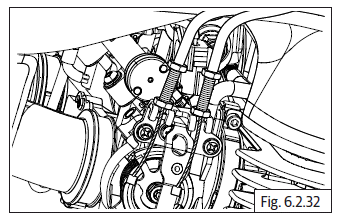
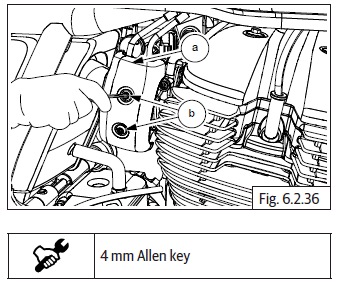
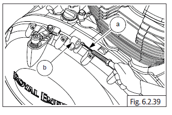
- Position inner cable (a) to the front slot of the rotor on throttle body, insert inner cable into the eyelet and route the cable in the groove in the rotor of the throttle body.
- Repeat above steps to locate the other cable in the rear slot of the rotor on throttle body.
- Ensure both inner cables are seated properly in the eyelets at throttle body end and handlebar end. Gently rotate throttle rotor at handlebar and ensure they are operating properly.
Throttle Cables Free Play Adjustment
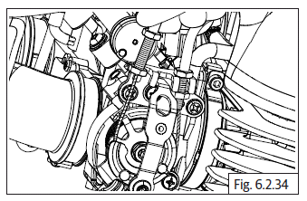
- Gently pull adjusters out of the bracket on throttle body end till the inner cables have NO SLACK.
- Tighten the outside nuts on the adjusters till they are resting against the bracket on throttle body.
- Hold handlebar straight and check for free rotation of 3 to 4 mm. (The rotor on the throttle body should not rotate).
- Loosen/Tighten the outer nuts to achieve the correct free play.
- Check both cables are correctly positioned and clamped to the frame, turn handlebar to both left and right sides to ensure the free play is maintained.
- Tighten inner lock nuts on the adjusters till they are firmly locked on the inside of the bracket.
NOTE
- To carry out finer adjustments to maintain the free play, turn the adjusters on the cables at the handlebar end, in or out.
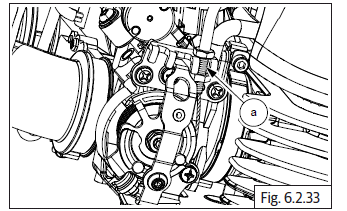
- Locate throttle body cover RH (a) against the bracket and ensure holes are aligned and tighten with 2 Nos. Hex socket screws (M5) (b).
- Assemble fuel tank assembly.
Clutch Cable
Handlebar End
- Ensure adjuster on lever bracket LH is in midway position and the slot in the adjuster is correctly aligned to the slot in the lever bracket LH.
- Locate inner cable into the eyelet on clutch lever and ensure it is aligned.
- Route inner cable into the slot in the clutch bracket and adjuster and lock the outer cable into adjuster.
- Route clutch cable between headlamp holder LH and frame towards the RH side.
- Locate 2 holding clips on the clutch cable and frame near RH exhaust pipe.
Clutch cover End
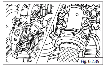
- Insert inner cable into the cable guide (b) in clutch cover assembly and ensure the adjuster (a) is fully inside the guide in clutch cover assembly.
- Assemble adjuster nut (a) on the adjuster and tighten by a few threads.
- Assemble protective rubber boot (a) on clutch cable inner (b).
- Gently locate inner cable (a) into clevis (b) in clutch lever (c).
Clutch Cable Free Play Adjustment
- Gently pull clutch cable adjuster (a) out of the clutch cover till the inner cable has NO SLACK and tighten the outer lock nut (b) against the guide in clutch cover.
- Hold handlebar straight and check clutch lever free play of 2 to 3 mm (The lever on clutch cover should not move).
- Loosen/Tighten outer nut at clutch cover end to achieve the correct free play.
- Check for proper clamping of clutch cable to frame, turn handlebar to both left and right sides to ensure the free play is maintained.
- Tighten inner lock nut on the adjuster till it is firmly locked against the cable guide on cover RH.
NOTE
- To carry out finer adjustments to maintain the free play, turn the adjuster on the lever bracket LH at the handlebar end, in or out.
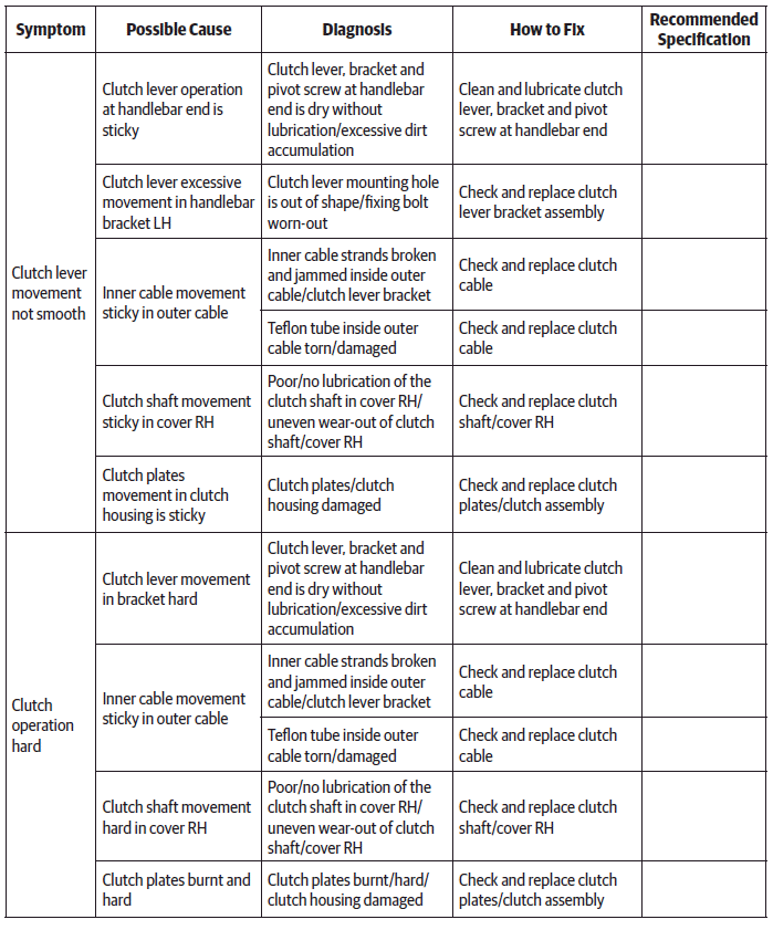
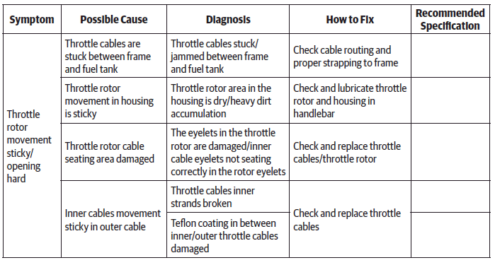
Troubleshooting
See also:
 Royal Enfield Interceptor 650 - Service manual > Throttle Cable
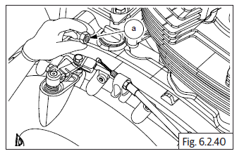
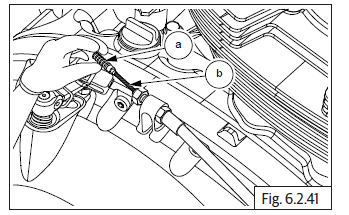
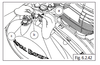
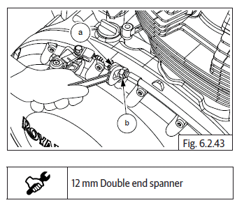
Throttle Body End CAUTION Ensure the motorcycle is upright on a firm and flat surface. Ensure Ignition switch and Engine stop switch are in OFF position. Remove side panel RH. Remove rider seat. Loosen fuel tank assembly mountings and carefully slide and lift fuel tank up to access 2 clips holding the throttle cables to frame on RH side. Gently compress and release the clip (a) holding throttle cable to frame on the RH side. Loosen and remove 2 Nos. Hex socket screws (M5) (a) on throttle body cover RH (b) and remove cover. Loosen 2 Nos. Hex nuts (M6) (a) fully on top of throttle cable bracket (b) to increase inner cable (c) free play. Push cable adjusters fully into the bracket and loosen the 2 inner hex nuts (M6) on the throttle cable adjusters. Ensure both inner nuts are free from the adjusters and gently pull out the adjuster of the inside cable till it is out of the bracket and slide the inner cable out through the slot in the bracket. Repeat above process for the other throttle cable. Rotate inner cable (a) till it is aligned with the slot in the rotor (b) on throttle body and remove cable from the eyelet. Repeat above process for removing the other throttle cable. Remove the cables from the bracket on throttle body.
Royal Enfield Interceptor 650 - Service manual > Handlebar
Handlebar - Continental GT Handlebar - Interceptor
 Rider's Manual BMW R 1250 GS GSA
 Owner's Manual Harley-Davidson Sportster XL1200X Forty-Eight
 Owner's Manual Honda CBR650R
 Service manual Honda CBR650
 Owner's Manual Honda PCX125
 Owner's Manual Kawasaki Z1000SX
 Service manual Kawasaki Z1000SX
 Owner's Manual Lexmoto Echo
 Owner's Manual Royal Enfield Interceptor 650
 Service manual Royal Enfield Interceptor 650
 Owner's Manual Yamaha MT-07