 Royal Enfield Interceptor 650 - Service manual > Handlebar
Handlebar - Continental GT
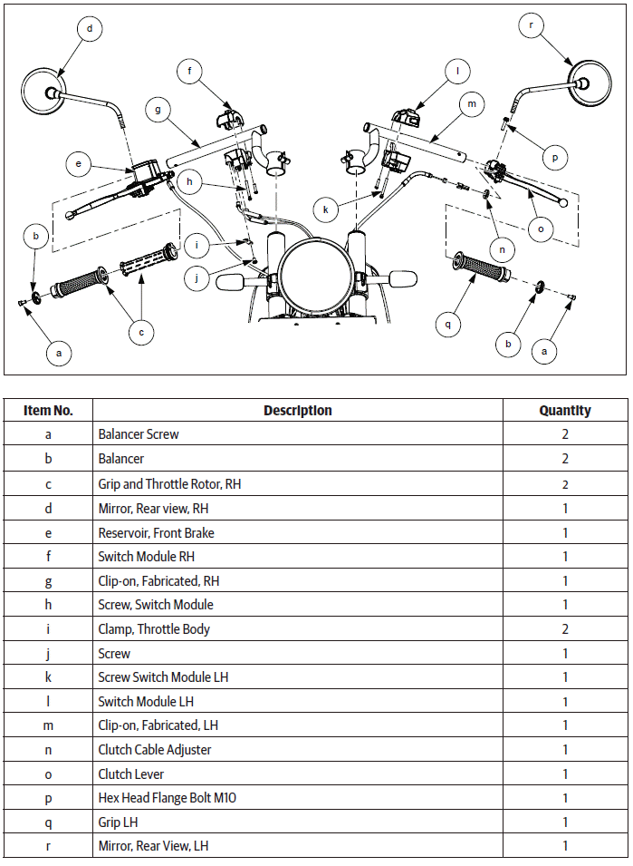
Handlebar - Interceptor
Dismantling
Aggregates of Handlebar
- Remove the following parts:
- Throttle cable.
- Clutch cable.
- Brake master cylinder front.
- Electrical connections on LH and RH handlebars.
- Cable routing straps.
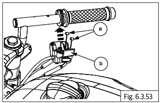
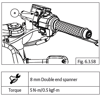
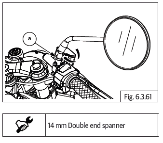
- Lift dust cup (a), loosen Hex nut (M8) (b) and rotate rear view mirror LH in clockwise direction.
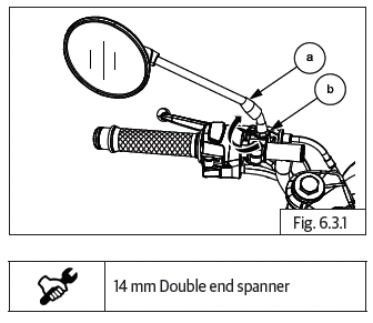
CAUTION Left hand thread! DO NOT rotate the mirror after it comes to stop on the bracket as it will cause the bracket to crack.
Always position mirror and lock in place with rider seated on the motorcycle.
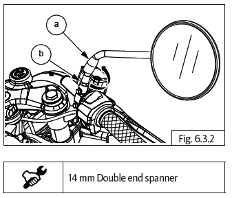
- Lift dust cup (a), loosen Hex nut (M8) (b) and rotate rear view mirror RH in anticlockwise direction.
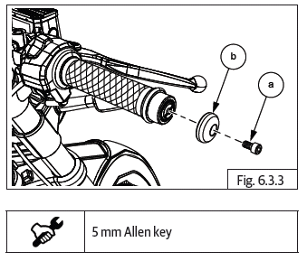
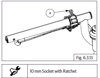
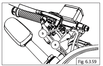
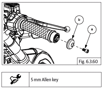
- Loosen and remove Hex socket bolt (M6) (a) along with balancer (b) from handlebar RH.
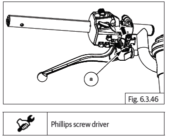
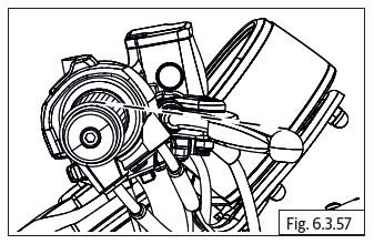
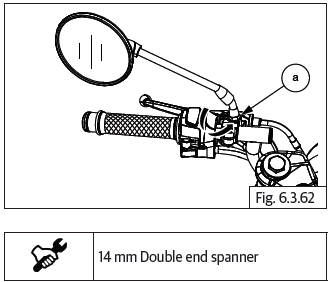
- Disconnect brake lamp switch connectors (a) from front brake switch (b).
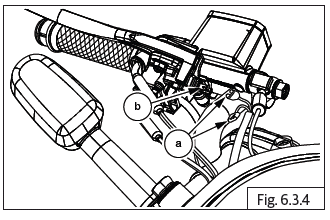
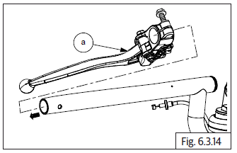
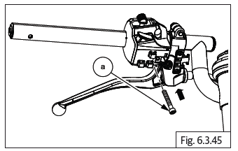
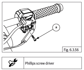
- Loosen and remove 2 Nos. Hex flange head bolt (M5) (a) to remove master cylinder assembly along with cap.
CAUTION Ensure master cylinder assembly is supported after removing.
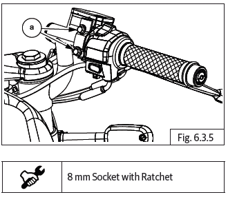
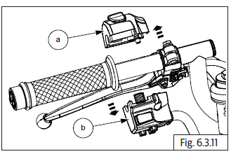
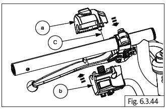
- Loosen and remove 2 Nos. Switch module screws (a) from RH handlebar.
- Gently separate switch module (a) top and bottom (b) from handlebar RH.
CAUTION Support RH switch module carefully after removal.
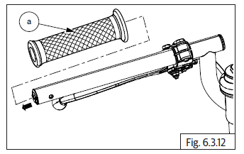
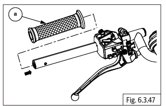
- Disconnect throttle cables.
- Gently remove throttle rotor (a) from the handlebar RH (b).
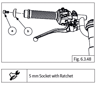
- Loosen and remove Hex socket head bolt (M6) (a) along with balancer (b) from handlebar LH.
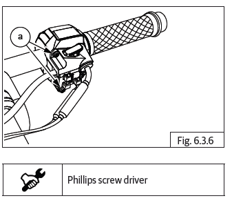
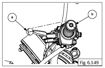
- Loosen and remove 2 Nos. screws (a) from switch module on handlebar LH.
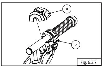
- Gently separate top (a) and bottom (b) switch module and remove from handlebar LH.
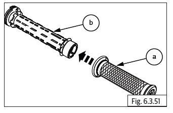
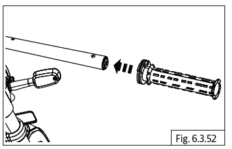
- Wrap a cloth soaked in hot water on grip LH (a). Allow time for the grip to become free on handlebar. Gently rotate anti-clockwise and simultaneously pull out from handlebar LH.
- Disconnect clutch cable connections from handlebar LH.
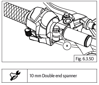
- Loosen Hex flanged head bolt (M6) (a) sufficiently on clutch lever bracket LH.
- Gently rotate and pull out clutch lever bracket LH (a) from handlebar (clip-on) LH.
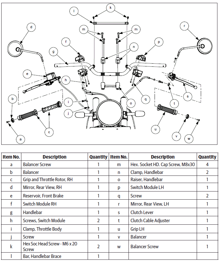
Handlebar - Interceptor
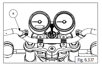
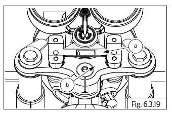
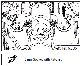
- Loosen and remove 4 Nos. Hex socket bolts (M8) (a) from clamps on handlebar.
- Remove 2 Nos. clamps (a) from raiser handlebar.
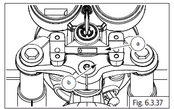
- Remove handlebar (a) from raiser handlebar.
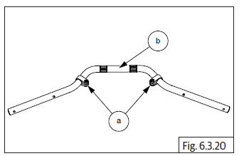
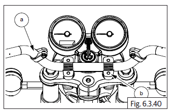
- Loosen and remove 2 Nos. Hex head flanged bolts (M10) (a) from yoke top and raiser handlebar (b).
- Remove raiser handlebar (a) from yoke top (b).
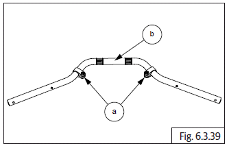
- Remove clamp handlebar brace (a) from handlebar (b).
Top Yoke
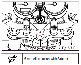
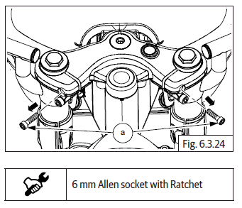
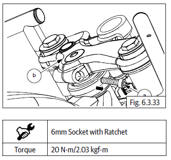
- Loosen and remove 2 Nos. Hex socket bolts (M6) (a) holding ignition switch (b) from top yoke.
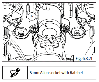
- Remove ignition switch (a) from top yoke.
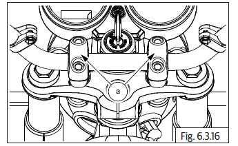
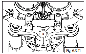
- Loosen and remove 2 Nos. Hex socket bolts (M8) (a) holding instrument cluster bracket from top yoke.
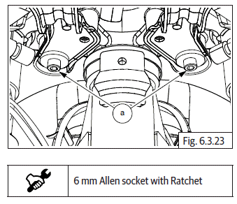
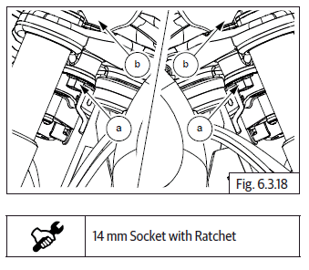
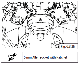
- Loosen 2 Nos. Hex socket bolts (M8) (a) sufficiently on LH and RH sides of top yoke.
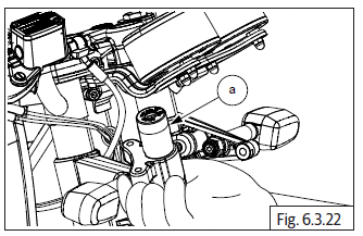
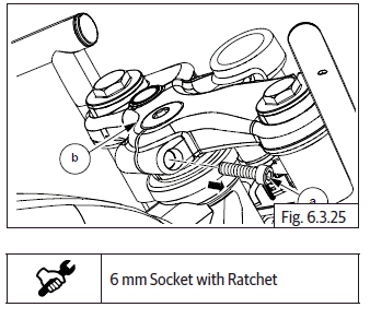
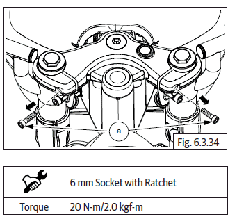
- Loosen and remove Hex socket head bolt (M8) (a) from top yoke (b) RH.
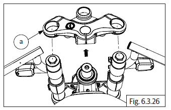
- Gently tap and pull out top yoke (a) from LH and RH fork assembly.
Handlebar LH and RH - Continental GT
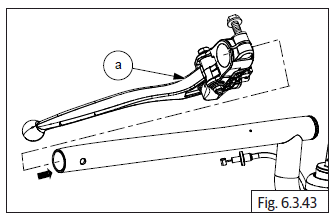
- Gently remove RH handlebar (a) from RH fork (b).
- Gently remove LH handlebar (a) from LH fork (b).
Inspection
- Inspect handlebar LH and RH for any bends, cracks or damages. Replace if necessary.
- Inspect rubber grip tightness and replace if it has lost grip.
Assembly
Handlebar LH and RH - Continental GT
- Locate LH Handlebar (a) over LH fork assembly (b) with the locating peg facing upwards.
- Locate RH handlebar (a) over RH fork assembly (b) with the locating peg facing upwards.
Top Yoke
- Locate top yoke (a) on the LH and RH fork assembly and ensure the locating peg on LH and RH handlebars are seated properly in the top yoke.
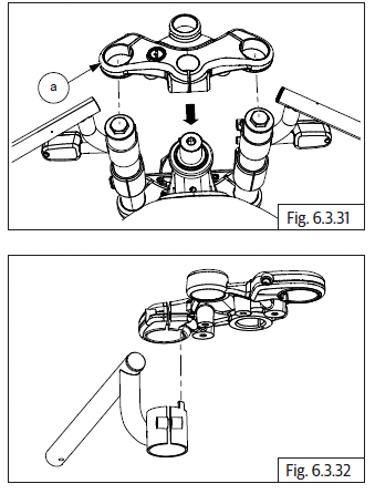
- Insert and tighten Hex socket head bolt (M8) (a) on top yoke RH (b).
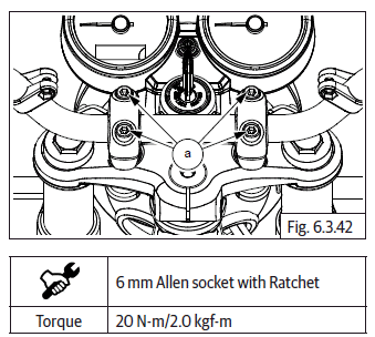
- Insert and tighten 2 Nos. Hex socket bolts (M8) (a) into top yoke.
- Position the instrument cluster mounting bracket on top yoke, align the mounting holes and tighten bracket to top yoke with 2 Nos. Hex socket head bolts (M8) (a).
- Insert ignition switch into top yoke from bottom, align mounting holes and tighten ignition switch (a) to top yoke with 2 Nos. Hex socket bolts (M6) (b).
Handlebar - Interceptor
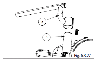
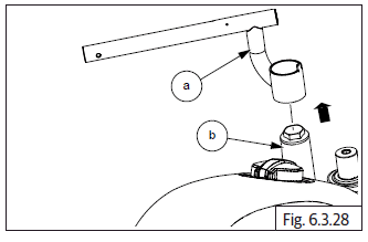
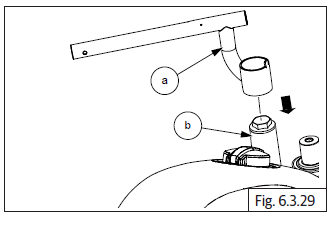
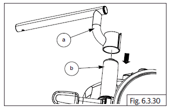
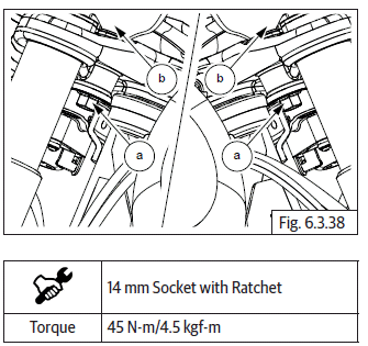
- Locate raiser handlebar (a) into yoke top (b).
- Locate and tighten 2 Nos. Hex flange head bolts (M10) (a) into yoke top and raiser handlebar (b).
- Assemble clamps handlebar brace (a) into handlebar (b).
- Assemble handlebar (a) into raiser handlebar (b).
- Install clamp handlebar (a) into handlebar.
NOTE
- Ensure the steering handlebar align marks/dots are matched with clamp handlebar parallel.
- Locate and tighten 4 Nos. Hex socket bolts (M8) (a) into clamp handlebar.
Aggregates of Handlebar
- Insert clutch lever bracket (a) on LH handlebar till the mounting hole switch module is visible.
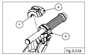
- Assemble switch module top (a) and bottom (b) on handlebar LH. Ensure peg (c) on LH switch module top half is correctly located in the hole in handlebar.
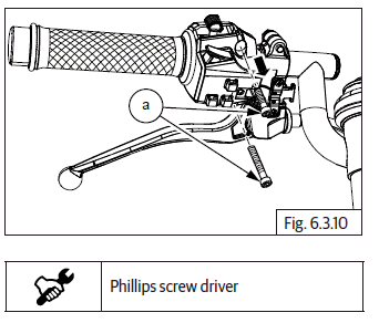
- Insert the long screw (a) into front mounting hole of switch module LH from bottom and tighten just sufficiently.
- Insert short screw (a) into rear mounting hole of switch module LH from bottom and tighten just sufficiently. Tighten both screws evenly and completely.
CAUTION DO NOT over tighten.
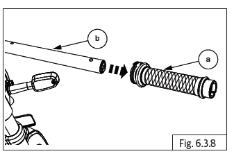
- Soak grip into hot water for a few minutes and assemble grip (a) on LH handlebar till it rests on the switch module.
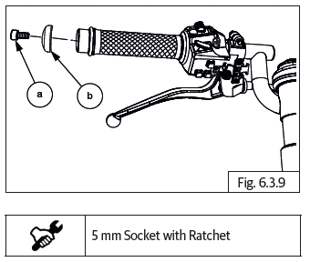
- Insert and tighten Hex socket head bolt (M6) (a) along with balancer (b) into handlebar LH.
- Position clutch lever bracket against switch module LH and ensure clutch lever (a) is slightly lower than hand grip LH (b).
- Tighten Hex head bolt (M6) (a) on lever bracket LH just sufficiently, duly ensuring bracket does not rotate on handlebar.
CAUTION DO NOT over tighten bolt as it will cause bracket to crack.
- Assemble clutch cable.
- Gently install grip (a) into throttle rotor (b) RH.
- Lubricate throttle rotor grip inside with general purpose grease and assemble on handlebar RH.
- Ensure the cable slots on the rotor are facing above for correct and ease of assembly of inner cables.
- Insert throttle cables (a) into the bottom housing of switch module RH with dummy plug (b).
- Connect throttle cables to throttle rotor grip.
- Assemble switch module top (a) and bottom (b) on handlebar RH. Ensure peg (c) on RH switch module top half is correctly located in the hole in handlebar.
- Insert long screw (a) into the front mounting hole of switch module RH from the bottom and tighten just sufficiently.
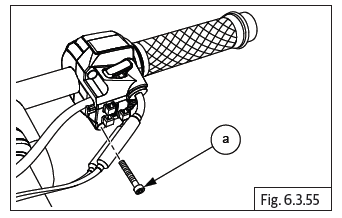
- Insert the short screw (a) into the rear mounting hole of switch module RH from the bottom and tighten just sufficiently. Tighten both screws evenly and completely.
CAUTION DO NOT over tighten.
- Position the master cylinder bracket against the switch module RH, ensure the lever is slightly lower than the throttle rotor RH.
- Locate clamp on handlebar RH and tighten 2 Nos. Hex head bolts (M5) (a) just sufficiently, duly ensuring bracket does not rotate on handlebar. DO NOT OVER TIGHTEN.
- Connect brake lamp switch connectors (a) to master cylinder pins (b).
- Insert and tighten Hex socket bolt (M6) (a) along with balancer (b) on handlebar RH.
- Ensure lock nut on mirror RH stem is fully tightened.
- Locate thread portion of rear view mirror stem (a) on threads on master cylinder bracket, rotate clockwise till mirror comes to stop.
- Rotate mirror clockwise for adjusting the view and tighten lock nut (M8) against bracket.
CAUTION DO NOT rotate the mirror after it comes to stop on the bracket as it will cause the bracket to crack.
Always position mirror and lock in place with rider seated on the motorcycle.
- Ensure lock nut on mirror LH stem is fully tightened.
- Locate threaded portion of rear view mirror stem (a) on threads on clutch lever cylinder bracket, rotate anticlockwise till mirror comes to stop.
- Rotate mirror clockwise for adjusting the view and tighten lock nut (M8) against bracket.
CAUTION Left hand thread DO NOT rotate the mirror after it comes to stop on the bracket as it will cause the bracket to crack.
Always position mirror and lock in place with rider seated on the motorcycle.
- After assembly, check proper functioning of electrical components.
Troubleshooting
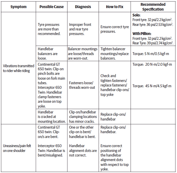
NOTE
- The troubleshooting given in this section is only related to issues with Handlebar. For complaints like unstable riding, wobbling, etc., it will be necessary to check other aggregates like wheel, front/rear suspension and so on.
See also:
 Royal Enfield Interceptor 650 - Service manual > Throttle Body End
Gently open throttle at handlebar end and identify the cable in which the inner cable retracts. Insert this cable into the front slot in the bracket in the throttle body and ensure the adjuster is fully into the bracket on throttle body. Assemble lock nut on the inner cable. Position inner cable (a) to the front slot of the rotor on throttle body, insert inner cable into the eyelet and route the cable in the groove in the rotor of the throttle body. Repeat above steps to locate the other cable in the rear slot of the rotor on throttle body. Ensure both inner cables are seated properly in the eyelets at throttle body end and handlebar end. Gently rotate throttle rotor at handlebar and ensure they are operating properly.
Royal Enfield Interceptor 650 - Service manual > Exhaust Pipes and Silencers
Dismantling Hego/Oxygen Sensor Connectors Disconnect Hego/oxygen sensor connectors (a) from both LH and RH on the front side of engine.
 Rider's Manual BMW R 1250 GS GSA
 Owner's Manual Harley-Davidson Sportster XL1200X Forty-Eight
 Owner's Manual Honda CBR650R
 Service manual Honda CBR650
 Owner's Manual Honda PCX125
 Owner's Manual Kawasaki Z1000SX
 Service manual Kawasaki Z1000SX
 Owner's Manual Lexmoto Echo
 Owner's Manual Royal Enfield Interceptor 650
 Service manual Royal Enfield Interceptor 650
 Owner's Manual Yamaha MT-07