 Royal Enfield Interceptor 650 - Service manual > Auto Chain Tensioner
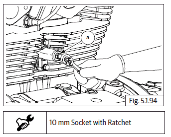
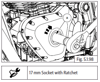
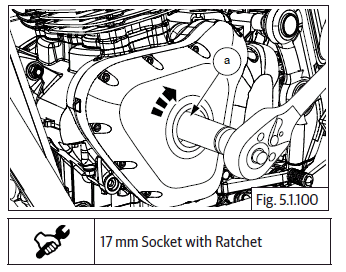
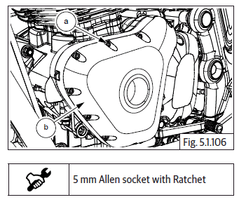
- Loosen and remove Hex flange head bolt (M6) (a) from the auto chain tensioner.
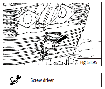
- Insert a small screw driver into chain tensioner and loosen until timing chain slack is at the maximum.
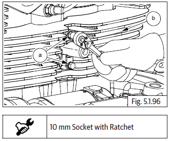
- Loosen and remove 2 Nos. Hex flange head bolts (M6) (a) to remove auto chain tensioner from cylinder barrel (b).
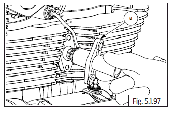
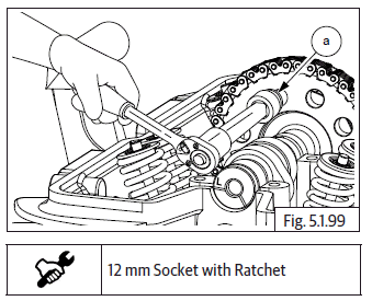
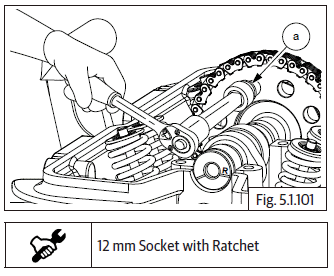
- Remove auto timing chain tensioner (a) from cylinder barrel along with gasket.
Camshaft Sub Assembly
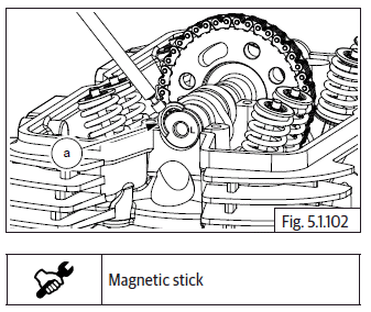
- Rotate magneto rotor (a) till one of Hex head bolts on cam chain sprocket appears at top most position.
- Loosen and remove 1 st Hex flange head bolt (M8) (a) from cam sprocket.
- Rotate magneto rotor (a) in clockwise direction till other bolt is visible at top most position.
- Loosen and remove 2 nd Hex head bolt (M8) (a) from cam sprocket.
- Remove "C" washer (a) from groove in cylinder head LH to release cam shaft.
- Gently release the cam chain (a) from the cam sprocket (b).
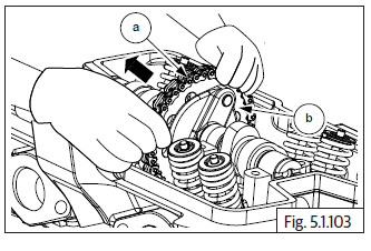
- Gently lift camshaft with sprocket (b) and remove from cylinder head.
- Support cam chain (a) suitably while removing camshaft, to prevent it from falling into crankcase.
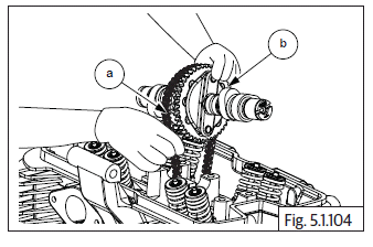
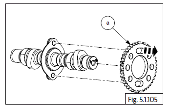
- Remove sprocket (a) from camshaft.
Magneto Cover
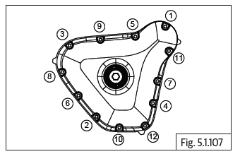
- Loosen and remove 12 Nos. Hex socket head bolts (M6) (a) in crisscross pattern to remove magneto cover (b) from crankcase on LH side.
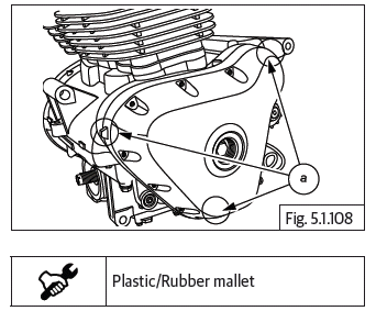
- The magneto cover may be hard to remove from crankcase, due to the magnetic force from the magneto acting on the stator coil.
- Gently tap on the tabs (a) with a plastic / rubber mallet, on the inside edges of the magneto cover, to remove.
- Remove the 2 Nos. dowel pins (a) and (b) from the crankcases/magneto cover.
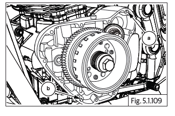
- Remove gasket (a).
CAUTION Do not use a sharp tool to scrap the gasket material from the joint faces.
If required scrap only with a soft and blunt tool.
See also:
 Royal Enfield Interceptor 650 - Service manual > Reed Valves
Disconnect the hose (a) from the reed valve tube on the front side of cylinder head. Loosen and remove 4 Nos. Hex socket head screws (M6) (a) holding reed valves to cylinder head. Remove reed valve (a) from the cylinder head.
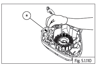
Royal Enfield Interceptor 650 - Service manual > Stator Assembly with CPS
Stator Assembly with Crank Position Sensor Loosen and remove 3 Nos. Hex socket head screws (M6) (a) holding the stator assembly (b). Loosen and remove 2 Nos. Hex socket head screws (M6) (a) on guide plate (b) holding crank position sensor to magneto cover. Remove guide plate (a) from magneto cover sub assembly. Gently release wiring grommet (a) from magneto cover. Gently remove stator assembly (b) from magneto cover.
 Rider's Manual BMW R 1250 GS GSA
 Owner's Manual Harley-Davidson Sportster XL1200X Forty-Eight
 Owner's Manual Honda CBR650R
 Service manual Honda CBR650
 Owner's Manual Honda PCX125
 Owner's Manual Kawasaki Z1000SX
 Service manual Kawasaki Z1000SX
 Owner's Manual Lexmoto Echo
 Owner's Manual Royal Enfield Interceptor 650
 Service manual Royal Enfield Interceptor 650
 Owner's Manual Yamaha MT-07