 Royal Enfield Interceptor 650 - Service manual > Stator Assembly with CPS
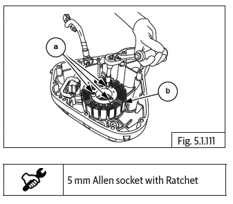
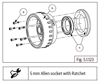
Stator Assembly with Crank Position Sensor
- Loosen and remove 3 Nos. Hex socket head screws (M6) (a) holding the stator assembly (b).
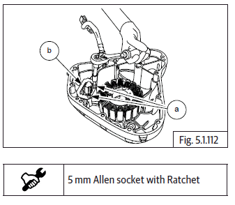
- Loosen and remove 2 Nos. Hex socket head screws (M6) (a) on guide plate (b) holding crank position sensor to magneto cover.
- Remove guide plate (a) from magneto cover sub assembly.
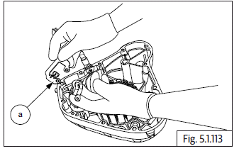
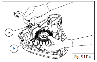
- Gently release wiring grommet (a) from magneto cover.
- Gently remove stator assembly (b) from magneto cover.
Magneto Rotor Bolt
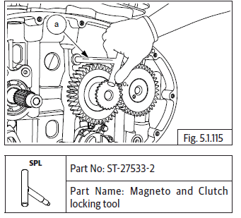
- In order to loosen magneto rotor bolt, it will be necessary to remove clutch cover.
- Ensure LH piston is at TDC on compression stroke.
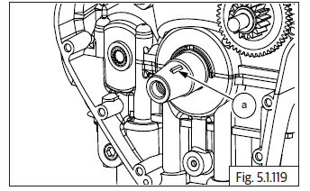
- Insert special tool (a) in crankcase RH to lock the crankshaft and prevent rotation.
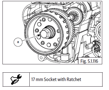
- Loosen and remove Hex flange head bolt (M12) (a).
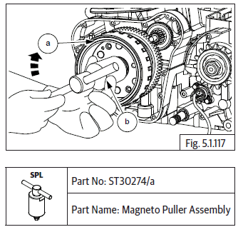
- Ensure center bolt of magneto rotor puller is loosened sufficiently.
- Assemble puller (b) on magneto rotor (a) and thread it in fully.
- Tighten center bolt onto puller till magneto rotor gets released from crankshaft.
- Gently pull out magneto rotor assembly (a) with starter clutch.
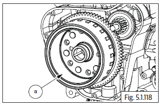
- Remove woodruff key (a) from crankshaft.
Starter Clutch from Magneto Rotor
-
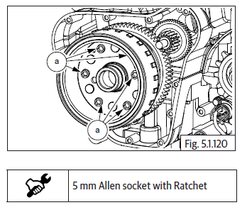
Slightly loosen 6 Nos. Hex socket head screws (M6) (a) from inside magneto rotor. DO NOT LOOSEN AND REMOVE FULLY.
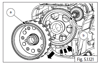
- Remove magneto rotor assembly (a) from carnk shaft, hold the rotor firmly, rotate gear starter clutch (b) anti-clockwise and pull out simultaneously to separate rotor from the gear.
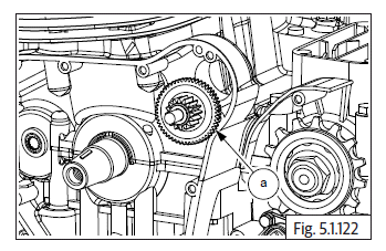
- Remove starter idle gear (a).
- Loosen and remove 6 Nos. Hex socket head screws (M6) (a) from inside magneto rotor (b) and separate one way clutch with outer ring (c).
- Remove one way clutch from outer ring.
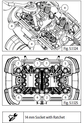
Cylinder Head
- Remove exhaust pipe and silencers LH and RH.
- Loosen and remove 8 Nos. Hex head long bolts (M10) (a) in crisscross pattern on cylinder head.
- Support cam chain suitably and gently remove cylinder head (a) from cylinder barrel (b).
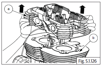
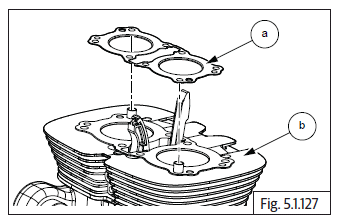
- Remove the cylinder head gasket (a) from cylinder barrel (b).
See also:
 Royal Enfield Interceptor 650 - Service manual > Auto Chain Tensioner
Loosen and remove Hex flange head bolt (M6) (a) from the auto chain tensioner. Insert a small screw driver into chain tensioner and loosen until timing chain slack is at the maximum. Loosen and remove 2 Nos. Hex flange head bolts (M6) (a) to remove auto chain tensioner from cylinder barrel (b). Remove auto timing chain tensioner (a) from cylinder barrel along with gasket.
Royal Enfield Interceptor 650 - Service manual > Components from Cylinder Head
Valves and Springs Compress valve spring with special tool (a). Remove the cotters (a) on valve stem at the top. Gently loosen the screw on valve spring compressor, till the valve spring tension is completely released and remove the special tool.
 Rider's Manual BMW R 1250 GS GSA
 Owner's Manual Harley-Davidson Sportster XL1200X Forty-Eight
 Owner's Manual Honda CBR650R
 Service manual Honda CBR650
 Owner's Manual Honda PCX125
 Owner's Manual Kawasaki Z1000SX
 Service manual Kawasaki Z1000SX
 Owner's Manual Lexmoto Echo
 Owner's Manual Royal Enfield Interceptor 650
 Service manual Royal Enfield Interceptor 650
 Owner's Manual Yamaha MT-07