 Royal Enfield Interceptor 650 - Service manual > Components from Cylinder Head
Engine / Components Removal from Engine / Components from Cylinder Head
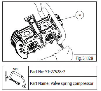
Valves and Springs
- Compress valve spring with special tool (a).
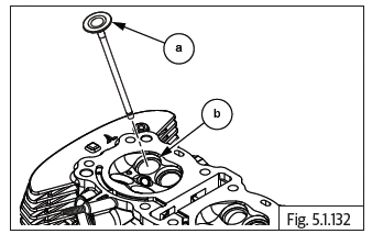
- Remove the cotters (a) on valve stem at the top.
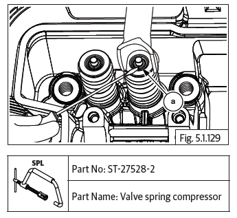
- Gently loosen the screw on valve spring compressor, till the valve spring tension is completely released and remove the special tool.
CAUTION Valve spring under high tension when compressed.
Release valve spring compressor tool slowly and with care.
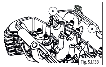
- Remove the retainer, valve spring (a) form the top of the valve spring (b).
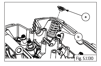
- Remove valve spring (a) from valve stem (b).
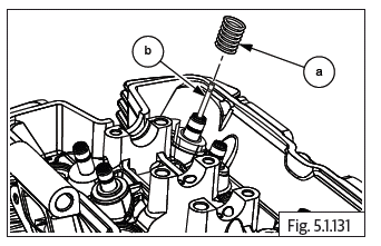
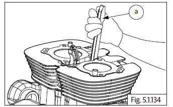
- Remove valve (a) from cylinder head (b) by pulling it out from the cylinder head inside.
- Remove valve stem seal (a) from valve guide (b).
- Follow the same procedure to remove the other valves from the cylinder head.
Floating Chain Pad
- Remove the floating chain pad (a) from front end of the cylinder barrel.
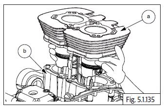
Cylinder Barrel
- Support cam chain suitably.
- Gently remove cylinder barrel (a) from crankcase (b).
Pistons
- Remove the circlip (a) from outer side of piston RH.
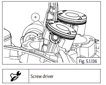
- Gently push out gudgeon pin (a) from inner side of piston RH and ensure it has completely come out of the connecting rod, to release piston RH from the connecting rod.
- Repeat above procedure for removing piston LH.
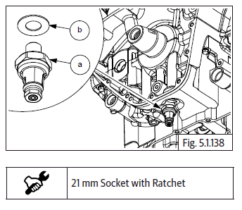
Oil Pressure Switch
- Ensure engine oil is drained completely.
- Loosen and remove pressure switch (a) along with washers (b) from bottom of the crankcase RH.
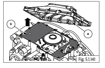
- Loosen and remove the 13 Nos. Hex bolts (M6) (a) in crisscross pattern from sump.
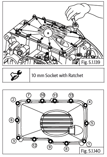
- Remove sump cover (a) along with gasket (b) from bottom crankcase.
Oil Strainer
- Loosen and remove 2 Nos. Hex flange head bolts (M6) (a) to remove oil strainer (b) along with O-ring (c).
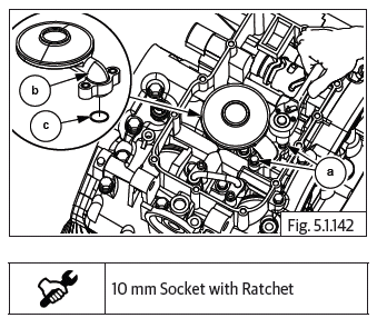
CAUTION DO NOT reuse O-ring. Always use new O-ring during installation.
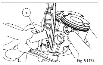
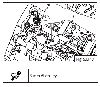
Oil Bypass
- Loosen and remove pan head screw (M6) (a) to remove bypass (b) from crankcase.
See also:
 Royal Enfield Interceptor 650 - Service manual > Stator Assembly with CPS
Stator Assembly with Crank Position Sensor Loosen and remove 3 Nos. Hex socket head screws (M6) (a) holding the stator assembly (b). Loosen and remove 2 Nos. Hex socket head screws (M6) (a) on guide plate (b) holding crank position sensor to magneto cover. Remove guide plate (a) from magneto cover sub assembly. Gently release wiring grommet (a) from magneto cover. Gently remove stator assembly (b) from magneto cover.
 Rider's Manual BMW R 1250 GS GSA
 Owner's Manual Harley-Davidson Sportster XL1200X Forty-Eight
 Owner's Manual Honda CBR650R
 Service manual Honda CBR650
 Owner's Manual Honda PCX125
 Owner's Manual Kawasaki Z1000SX
 Service manual Kawasaki Z1000SX
 Owner's Manual Lexmoto Echo
 Owner's Manual Royal Enfield Interceptor 650
 Service manual Royal Enfield Interceptor 650
 Owner's Manual Yamaha MT-07