 Kawasaki Z1000SX - Service manual > Crankshaft Sensor Installation
- Tighten:
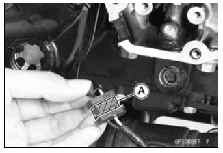
Torque - Crankshaft Sensor Bolts: 5.9 N*m (0.60 kgf*m, 52 in*lb) - Apply silicone sealant [A] to the crankshaft sensor lead grommet and
crankcase halves mating surface on the front and rear sides of the
crankshaft sensor cover mount.
Sealant - Liquid Gasket, TB1211F: 92104-0004
- Replace the O-ring [A] in the crankshaft sensor cover with a new one.
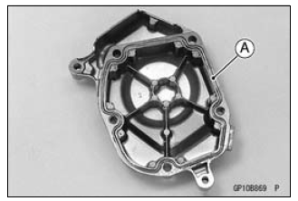
- Install:
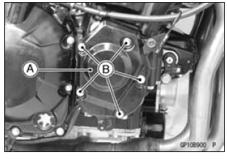
Crankshaft Sensor Cover [A] - Tighten:
Torque - Crankshaft Sensor Cover Bolts [B]: 12 N*m (1.2 kgf*m, 106 in*lb) - Run the crankshaft sensor lead correctly (see Cable, Wire, and Hose Routing section in the Appendix chapter).
- Confirm that the drain hose and clamp are installed securely and run the hose correctly (see Cable, Wire, and Hose Routing section in the Appendix chapter).
Crankshaft Sensor Inspection
- Remove:
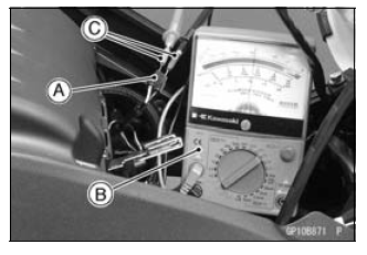
Crankshaft Sensor Lead Connector [A] (see Crankshaft Sensor Removal) - Set the hand tester [B] to the × 100 Ω range and connect (+) lead to the
yellow lead and (-) lead to the black lead in the connector.
Special Tools -
Hand Tester: 57001-1394
Needle Adapter Set [C]: 57001-1457
Crankshaft Sensor Resistance: 376 - 564 Ω
If there is more resistance than the specified value, the coil has an open lead and must be replaced. Much less than this resistance means the coil is shorted, and must be replaced.
- Using the highest resistance range of the tester, measure the resistance between the crankshaft sensor leads and chassis ground.
Any tester reading less than infinity (∞) indicates a short, necessitating replacement of the crankshaft sensor assembly.
Crankshaft Sensor Peak Voltage Inspection
NOTE
- Be sure the battery is fully charged.
- Remove:
Fuel Tank (see Fuel Tank Removal in the Fuel System (DFI) chapter)
Crankshaft Sensor Lead Connector [A] (see Crankshaft Sensor Removal) - Set the hand tester [B] to the DC 10 V range.
- Connect the peak voltage adapter [C] to the hand tester and crankshaft sensor leads in the connector.
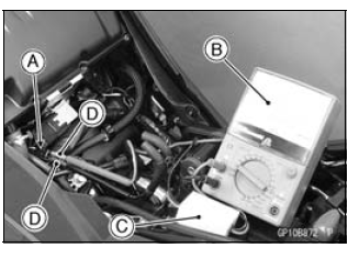
Special Tools -
Hand Tester: 57001-1394
Peak Voltage Adapter: 57001-1415
Type: KEK-54-9-B
Needle Adapter Set [D]: 57001-1457
Connections:
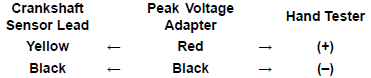
- Turn the ignition switch and engine stop switch ON.
- Pushing the starter button, turn the engine 4 - 5 seconds with the transmission gear in neutral to measure the crankshaft sensor peak voltage.
- Repeat the measurement 5 or more times.
Crankshaft Sensor Peak Voltage
Standard: 2.0 V or more
If the tester reading is not specified one, inspect the crankshaft sensor (see Crankshaft Sensor Inspection).
See also:
 Kawasaki Z1000SX - Service manual > Ignition System
WARNING The ignition system produces extremely high voltage. Do not touch the spark plug, ignition coil or ignition coil lead while the engine is running, or you could receive a severe electrical shock.
Kawasaki Z1000SX - Service manual > Timing Rotor Removal
Remove the crankshaft sensor (see Crankshaft Sensor Removal). Remove the timing rotor [A]. Holding the timing rotor with the flywheel & pulley holder [B] and remove the rotor bolt [C].
 Rider's Manual BMW R 1250 GS GSA
 Owner's Manual Harley-Davidson Sportster XL1200X Forty-Eight
 Owner's Manual Honda CBR650R
 Service manual Honda CBR650
 Owner's Manual Honda PCX125
 Owner's Manual Kawasaki Z1000SX
 Service manual Kawasaki Z1000SX
 Owner's Manual Lexmoto Echo
 Owner's Manual Royal Enfield Interceptor 650
 Service manual Royal Enfield Interceptor 650
 Owner's Manual Yamaha MT-07