 Kawasaki Z1000SX - Service manual > Timing Rotor Removal
- Remove the crankshaft sensor (see Crankshaft Sensor Removal).
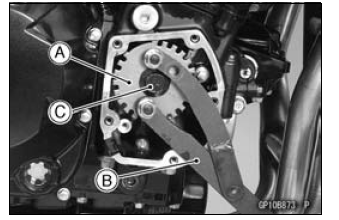
- Remove the timing rotor [A].
- Holding the timing rotor with the flywheel & pulley holder [B] and remove the rotor bolt [C].
Special Tool - Flywheel & Pulley Holder: 57001-1605
Timing Rotor Installation
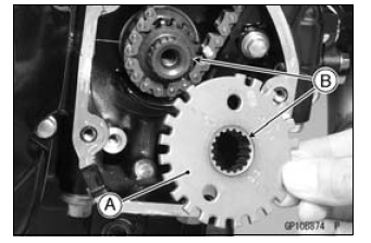
- Install the timing rotor [A] with the their theeth [B] aligned.
- Tighten:
Torque - Timing Rotor Bolt: 39 N*m (4.0 kgf*m, 29 ft*lb)
Special Tool - Flywheel & Pulley Holder: 57001-1605
Stick Coil Removal
NOTICE Never drop the stick coils, especially on a hard surface.
Such a shock to the stick coils can damage it.
- Remove:
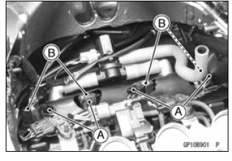
Air Cleaner Housing (see Air Cleaner Housing Removal in the Fuel System (DFI) chapter) - Disconnect the stick coil connectors [A].
- Pull the stick coils [B].
NOTICE Do not pry the connector part of the coil while removing the coil.
Stick Coil Installation
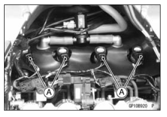
- Insert the coil as shown being careful of the coil heads [A] direction.
- Be sure the stick coils are installed by pulling up it lightly.
- Connect the connectors.
NOTICE Do not tap the coil head while installing the coil.
- Run the hoses and harness correctly (see Cable, Wire, and Hose Routing section in the Appendix chapter).
Stick Coil Inspection
- Remove the stick coils (see Stick Coil Removal).
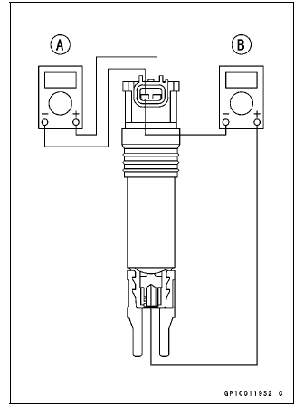
- Measure the primary winding resistance [A] as follows.
- Connect the hand tester between the coil terminals.
- Set the tester to the × 1 Ω range, and read the tester.
- Measure the secondary winding resistance [B] as follows.
- Connect the tester between the plug terminal and (-) coil terminal.
- Set the tester to the × 1 kΩ range and read the tester.
Stick Coil Winding Resistance
Primary Windings: 1.1 - 1.5 Ω
Secondary Windings: 10.8 - 16.2 kΩ
If the tester does not read as specified, replace the coil.
Stick Coil Primary Peak Voltage
NOTE
- Be sure the battery is fully charged.
- Remove the stick coils (see Stick Coil Removal), but do not remove the spark plugs.
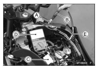
- Measure the primary peak voltage as follows.
- Install the new spark plug [A] into each stick coil [B], and ground them onto the engine.
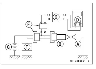
- Connect the peak voltage adapter [C] into the hand tester [D] which is set to the DC 250 V range.
- Connect the adapter to the lead wire-peak voltage adapter [E] which
is connected between the stick coil connector and stick coil.
ECU [F]
Battery [G]
Special Tools -
Hand Tester: 57001-1394
Peak Voltage Adapter: 57001-1415
Type: KEK-54-9-B
Lead Wire-Peak Voltage Adapter: 57001-1449
Primary Lead Connection
Adapter (R, +) to lead wire-peak voltage adapter (W)
Adapter (BK, -) to lead wire-peak voltage adapter (R)
WARNING To avoid extremely high voltage shocks, do not touch the spark plugs or tester connections.
- Turn the ignition switch and the engine stop switch ON.
- Pushing the starter button, turn the engine 4 - 5 seconds with the transmission in neutral to measure the primary peak voltage.
- Repeat the measurements 5 times for one stick coil.
Stick Coil Primary Peak Voltage
Standard: 100 V or more
- Repeat the test for the other stick coil.
If the reading is less than the specified value, check the following.
Stick Coils (see Stick Coil Inspection)
Crankshaft Sensor (see Crankshaft Sensor Inspection)
ECU (see ECU Power Supply Inspection in the Fuel System (DFI) chapter)
Spark Plug Removal
- Refer to the Spark Plug Replacement in the Periodic Maintenance chapter.
Spark Plug Installation
- Refer to the Spark Plug Replacement in the Periodic Maintenance chapter.
See also:
 Kawasaki Z1000SX - Service manual > Crankshaft Sensor Installation
Tighten: Torque - Crankshaft Sensor Bolts: 5.9 N*m (0.60 kgf*m, 52 in*lb) Apply silicone sealant [A] to the crankshaft sensor lead grommet and crankcase halves mating surface on the front and rear sides of the crankshaft sensor cover mount.
Kawasaki Z1000SX - Service manual > Spark Plug Condition Inspection
Remove the spark plugs (see Spark Plug Replacement). Visually inspect the spark plugs. If the spark plug center electrode [A] and/or side electrode [B] are corroded or damaged, or if the insulator [C] is cracked, replace the plug.
 Rider's Manual BMW R 1250 GS GSA
 Owner's Manual Harley-Davidson Sportster XL1200X Forty-Eight
 Owner's Manual Honda CBR650R
 Service manual Honda CBR650
 Owner's Manual Honda PCX125
 Owner's Manual Kawasaki Z1000SX
 Service manual Kawasaki Z1000SX
 Owner's Manual Lexmoto Echo
 Owner's Manual Royal Enfield Interceptor 650
 Service manual Royal Enfield Interceptor 650
 Owner's Manual Yamaha MT-07