 Royal Enfield Interceptor 650 - Service manual > Dismantling
Engine Control Unit (ECU)
CAUTION Before disconnecting ECU from the wiring harness, the battery terminals must be disconnected from the battery.
- Ensure the ignition switch and stop switch are in OFF position.
- Remove the following:
- Side panel RH.
- Side panel LH.
- Seat from frame.
- Disconnect battery terminals.
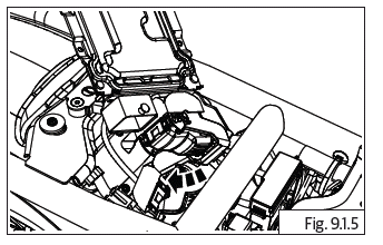
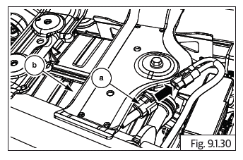
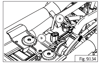
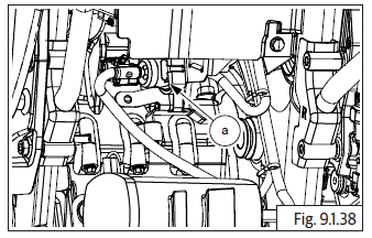
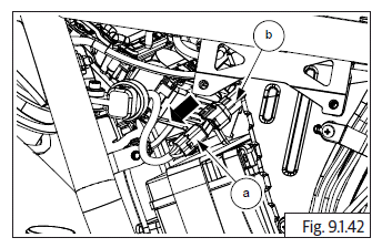
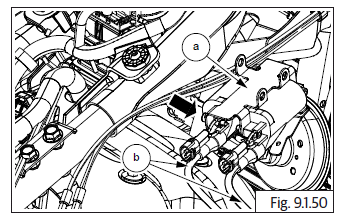
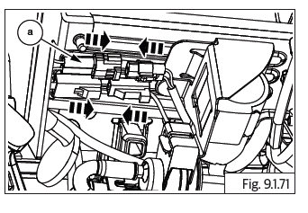
- ECU is main part of EMS and is located below seat assembly.
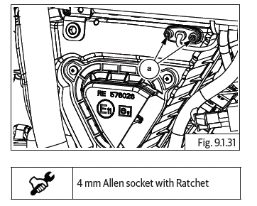
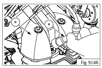
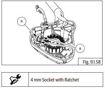
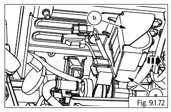
- Loosen and remove 4 Nos. flange Torx head screws (T20) (a) holding ECU (b) to infill cover.
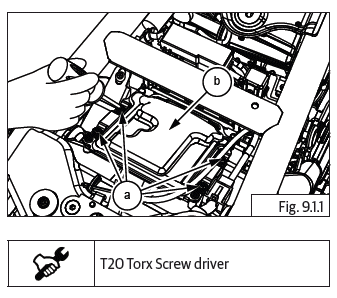
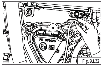
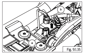
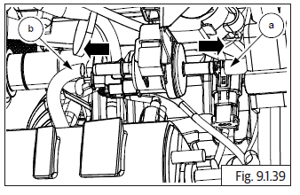
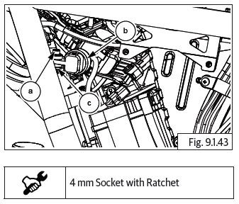
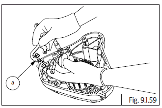
- Slightly lift up ECU and disconnect fuse box (a) and diagnosis on line (DOL) connector (b) with wiring harness from frame.
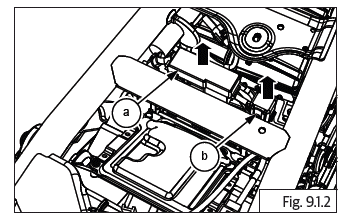
CAUTION DO NOT lift ECU too much as it will cause damage to the wiring connectors and wiring harness.
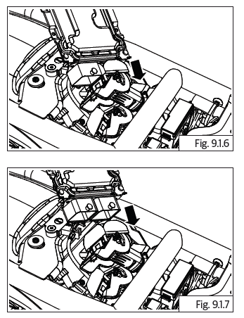
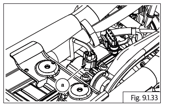
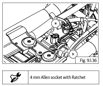
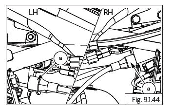
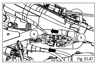
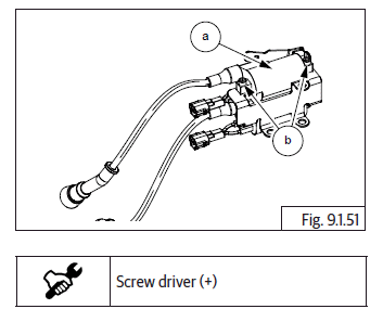
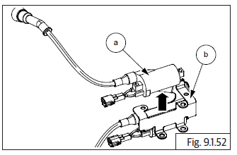
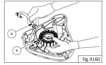
- Disconnect wiring harness connectors from ECU and remove ECU from frame. As below instructions.
- Hold ECU firmly.
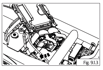
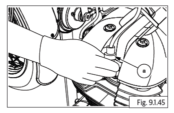
- Gently lift and release locks completely from connectors. Disconnect connectors from ECU.
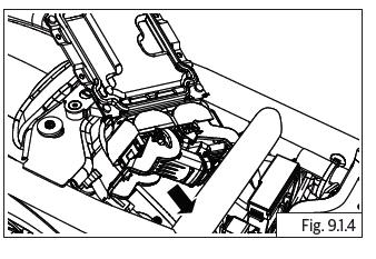
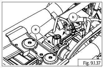
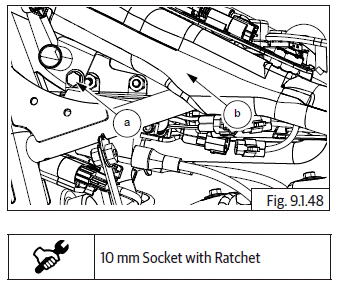
- Follow the same procedure for the other connector.
- Gently lift and release locks completely from connectors. Disconnect connectors from ECU.
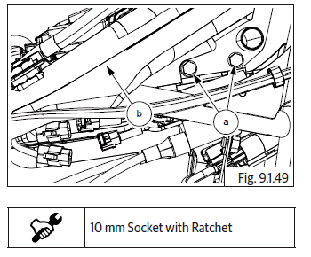
CAUTION Ensure locks are fully lifted up and released before disconnecting wiring connectors from ECU. Ensure locks are handled with care and do not get damaged or broken.
Damaged or broken locks will result in loose connections and cause the ECU to fail.
Storage of ECU
Do's & Don'ts
- Store ECU away from any magnetic forces at it will affect the ECU program software and damage ECU.
- Store ECU in a cool and dry place.
- DO NOT allow moisture to affect the ECU.
- DO NOT wash the ECU with water or any solvent.
- Prevent ECU from any external damages.
- DO NOT drop ECU or allow it to fall as internals will get damaged and render the ECU defective.
- DO NOT keep any heavy or sharp objects on ECU as it will damage internals and render the ECU defective.
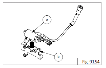
Fuel Pump
- Ensure Ignition switch and Engine stop switch are in OFF position
- Remove the following parts:
- Side panel RH.
- Rider seat.
- Fuel tank assembly.
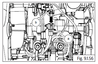
CAUTION Ensure the following: Fuel is drained completely from fuel tank. Fuel feed and return hoses are disconnected from the fuel rail.
Wiring couplers to fuel pump and low fuel sensor are disconnected. EVAP hose pipes are disconnected.
WARNING Gasoline is extremely flammable and highly explosive. Improper handling can lead to fatal accident or serious injury.
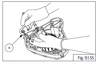
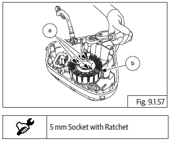
- Loosen and remove 6 Nos. Hex socket head bolts (M5) (a) holding fuel pump (b) to tank (c).
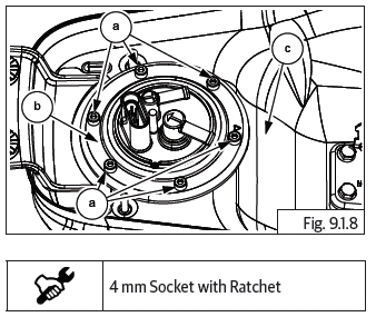
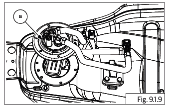
- Gently remove fuel pump (a) from fuel tank along with O-ring.
Manifold Absolute Pressure Sensor (MAP)
- Ensure ignition switch and engine stop switch are in OFF position
- Remove the following parts:
- Side panel RH.
- Rider seat.
- Fuel tank assembly.
CAUTION Ensure the following: Fuel is drained completely from fuel tank. Fuel feed and return hoses are disconnected from the fuel rail.
Wiring couplers to fuel pump and low fuel sensor are disconnected. EVAP hose pipes are disconnected.
WARNING Gasoline is extremely flammable and highly explosive. Improper handling can lead to fatal accident or serious injury.
- Remove throttle body cover from the LH side.
- Disconnect MAP sensor vacuum hose (a) from throttle body.
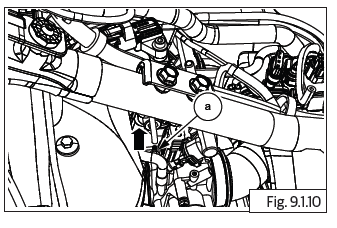
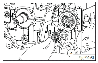
- The MAP sensor is fixed to the ABS modulator bracket.
- Loosen and remove Hex socket head bolt (M5) (a) along with washer, holding MAP sensor (b) to bracket.
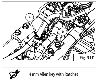
- Gently lift up MAP sensor to access wiring coupler.
- Push lock and release wiring harness connector (a) from MAP sensor connector (b) and disconnect the same.
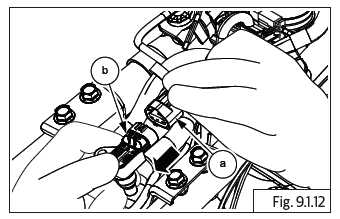
CAUTION DO NOT lift the MAP sensor too much to avoid damage to the wiring connectors.
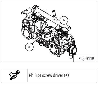
Throttle Body Assembly
- Ensure ignition switch and engine stop switch are in OFF position
- Remove the following parts:
- Side panel RH.
- Rider seat.
- Side panel LH.
- Fuel tank assembly.
CAUTION Ensure the following: Fuel is drained completely from fuel tank. Fuel feed and return hoses are disconnected from the fuel rail.
Wiring couplers to fuel pump and low fuel sensor are disconnected. EVAP hose pipes are disconnected.
WARNING Gasoline is extremely flammable and highly explosive. Improper handling can lead to fatal accident or serious injury.
- Remove the following parts:
- Throttle body cover LH and RH.
- Throttle cable.
- Remove electrical connectors from TPS, idle speed control stepper motor and fuel injectors LH and RH.
- Rubber hoses connecting to Throttle body from EVAP.
- Ensure vacuum hose and MAP sensor are removed from throttle body.
- Loosen wire clips on LH and RH air filter connection tubes.
- Loosen worm clip screw on inlet manifold on Cylinder (LH).
- Loosen worm clip screw on inlet manifold on Cylinder (RH).
NOTE
- Ensure both screws are sufficiently loosened and the worm clips rotates easily in the groove in the manifolds.
- Gently pull out throttle body from the inlet manifold rubbers along with fuel rail and injectors.
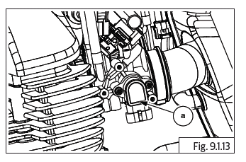
Throttle Position sensor (TPS)
- The TPS is located on left side of throttle body and should NOT BE REMOVED from the throttle body under any circumstances.
- In case of any defect in the TPS, complete throttle body assembly should be replaced.
CAUTION Do not disturb the TPS sensor (a) fixing screws or the throttle rotor setting screw as it will affect the EMS settings and the engine performance.
Fuel Injectors
- Remove throttle body.
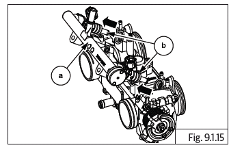
- Loosen and remove 2 Nos. button head screws (a) holding from fuel injector rail (b) to throttle body.
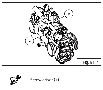
- Gently remove fuel rail (a) along with injectors (b) from throttle body.
- Gently release and remove lock clips (a) that secure injectors (b) to injector rail (c).
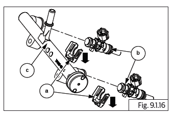
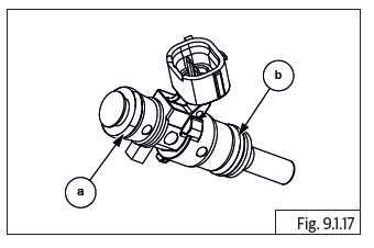
- Gently remove injectors from fuel rail along with O-rings upper (a) and lower (b).
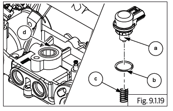
Idle Speed Control (ISC)
- Remove throttle body.
- The ISC motor is located on top of throttle body.
- Loosen and remove button head screw (a) from ISC stepper motor fixing clamp (b).
CAUTION The spring is loaded hence remove screw with care.
- Gently pull out and remove ISC stepper motor (a) along with O-ring (b) and spring (c) from throttle body (d).
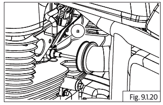
Engine Oil Temperature Sensor (EOT)
- Remove throttle body.
- The EOT (a) is located on the LH side cylinder head below the throttle body.
NOTE
- Ensure the engine is cold before dismantling EOT.
- Ensure Ignition switch and Engine stop switch are in OFF position.
CAUTION Do not remove EOT from cylinder head when the engine is hot.
- Remove throttle body cover LH.
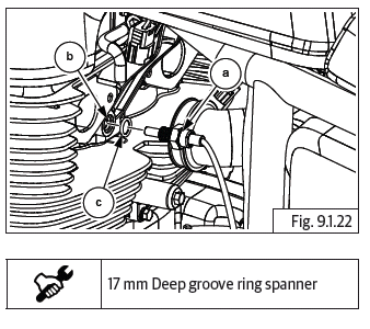
- Disconnect EOT sensor wiring coupler (a) from the main harness (b) above throttle body.
- Place a small tray under EOT to collect the oil when it is loosened and removed.
- Insert EOT wiring coupler through a deep grooved ring spanner and locate the spanner on the EOT hex head correctly.
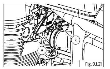
- Gently loosen EOT (a) from cylinder head (b) and remove along with O-ring (c).
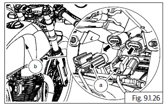
HEGO (O2) Sensor
CAUTION Do not loosen/remove HEGO (O2) sensors when the exhaust pipes are hot.
WARNING The engine and exhaust systems get extremely hot during normal operation and can result in serious burns if touched. Make sure exhaust pipes are not hot and is at the same levels of ambient/surrounding temperature whenever working on the engine or exhaust systems.
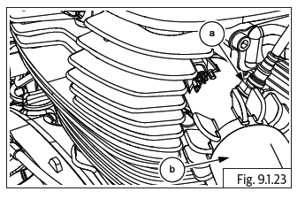
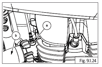
- The HEGO (O2) sensor (a) are located on the exhaust pipes (b) near the cylinder head RH.
- The HEGO (O2) sensor (a) are located on the exhaust pipes (b) near the cylinder head LH.
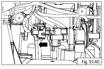
- Disconnect horn terminal couplers from the horns LH (a) and RH (b).
- Loosen and remove horn mounting bolts and remove LH and RH horns from frame.
- Disconnect HEGO (O2) sensor LH and RH sensor connectors (a) from wiring harness located under fuel tank (b).
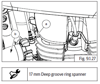
- Insert the LH HEGO (O2) sensor wiring coupler through a deep grooved ring spanner and locate the spanner on the sensor hex head correctly.
- Gently loosen LH HEGO (O2) sensor (a) from exhaust pipe (b) LH and remove along with Copper washer.
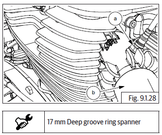
- Repeat process to remove RH HEGO (O2) sensor (a) from the RH exhaust pipe (b).
Intake Air Temperature (IAT)
- The IAT (a) assembled in the front RH side of the air filter housing.
- Ensure ignition switch and engine stop switch are in ''OFF'' position.
- Remove the following parts:
- Side panel RH.
- Rider seat.
- Side panel LH.
CAUTION Ensure the following: Fuel is drained completely from fuel tank. Fuel feed and return hoses are disconnected from the fuel rail.
Wiring couplers to fuel pump and low fuel sensor are disconnected. WARNING Gasoline is extremely flammable and highly explosive. Improper handling can lead to fatal accident or serious injury.
- Disconnect IAT sensor connector (a) from wiring harness located above air filter housing (b).
- Loosen and remove 2 Nos. Hex socket head cap screws (M5) (a) holding IAT sensor to air filter housing.
- Gently pull out IAT sensor (a) from air filter housing and remove sensor.
Secondary Air Injection Unit (Solenoid) or Air Cut Valve (ACV)
- The ACV (a) is assembled on the top RH side of the air filter housing.
- Ensure ignition switch and engine stop switch are in ''OFF'' position.
- Remove the following parts:
- Side panel RH.
- Rider seat.
- Side panel LH.
- Fuel tank assembly.
CAUTION Ensure the following: Fuel is drained completely from fuel tank. Fuel feed and return hoses are disconnected from the fuel rail.
Wiring couplers to fuel pump and low fuel sensor are disconnected. WARNING Gasoline is extremely flammable and highly explosive. Improper handling can lead to fatal accident or serious injury.
- Disconnect ACV hose (a) from valve (b).
- Disconnect ACV connector (a) from wiring harness connector (b) located above air filter assembly.
- Loosen and remove 2 Nos. Hex socket head cap screws (M5) (a) along with washer from ACV (b) from air filter.
- Gently pull out ACV (a) from air filter housing (b).
- Remove rubber grommet from air filter housing.
Purge Valve
- Remove the following parts:
- Side panel RH.
- Rider seat.
- Side panel LH.
- Engine control unit (ECU).
- Rear mudguard.
- Infill mudguard.
- Disconnect the roll over sensor connector.
- The purge valve (a) is part of the EVAP system and is located near battery tray bracket and connected to the throttle body bottom/side.
- Disconnect hose (a) connecting purge valve to throttle body.
- Disconnect hose (b) connecting purge valve to canister.
- Disconnect wiring coupler (a) from purge valve (b).
- Gently pull out purge valve from bracket.
Roll Over Sensor
- The Roll over sensor (a) is located on the rear mudguard infill.
- Ensure ignition switch and engine stop switch are in ''OFF'' position.
- Remove the following parts:
- Side panel RH.
- Rider seat.
- Disconnect roll over sensor wiring coupler (a) from main harness (b).
- Loosen and remove cap screw (M5) (a) holding roll over sensor (b) to frame (c) and remove roll over sensor.
Ignition Coil
- The Ignition coil (a) is located on the frame under fuel tank.
- Ensure Ignition switch and Engine stop switch are in ''OFF'' position.
- Remove the following parts:
- Side panel RH.
- Rider seat.
- Side panel LH.
CAUTION Ensure the following: Fuel is drained completely from fuel tank. Fuel feed and return hoses are disconnected from the fuel rail.
Wiring couplers to fuel pump and low fuel sensor are disconnected.
WARNING Gasoline is extremely flammable and highly explosive. Improper handling can lead to fatal accident or serious injury.
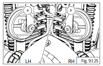
- Disconnect spark plug caps from the LH spark plug (a).
- Disconnect spark plug cap (a) from the RH spark plug.
- Disconnect wiring couplers (a) and (b) from the ignition coil on both LH and RH sides.
- Loosen and remove. Hex head collar bolts (M6) (a) from main frame LH (b).
- Support Ignition coil, loosen and remove 2 Nos. Hex head collar bolts (M6) (a) from main frame RH (b).
- Gently slide out Ignition coil (a) from frame and remove along HT cables (b).
Ignition Coil LH and RH from bracke
- Loosen and remove 2 Nos. slot head screws (M5) (a) holding ignition coil LH (b) to bracket.
- Separate ignition coil LH (a) from bracket (b).
- Loosen and remove 2 Nos. slot head screws (M5) (a) holding ignition coil RH (b) to bracket.
- Separate ignition coil RH (a) from bracket (b).
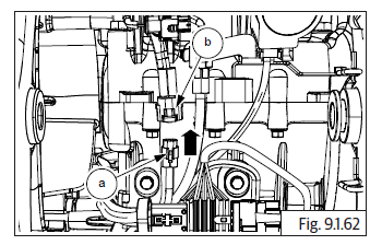
Crank Position Sensor
- The crank position sensor (a) is located inside the engine cover LH and attached to the stator coil.
- Ensure Ignition switch and Engine stop switch are in ''OFF'' position.
- Drain engine oil.
- Disconnect wiring coupler (a) of stator from main wiring harness (b).
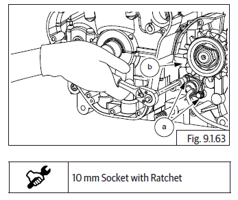
- Remove FD sprocket cover.
- Remove cover LH from Engine.
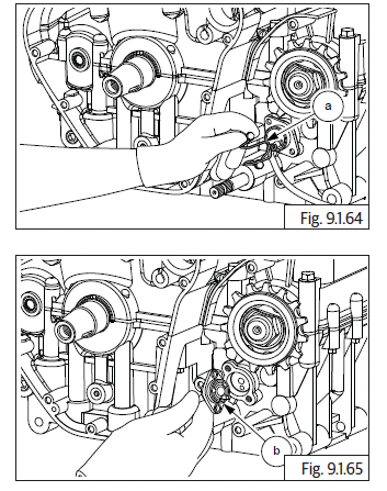
- Loosen and remove 3 Nos. Hex socket head screws (M6) (a) holding stator coil.
- Loosen and remove 2 Nos. Hex socket head bolts (M5) (a) holding crankshaft position sensor guide plate (b) to cover LH.
- Remove guide plate (a) from LH cover.
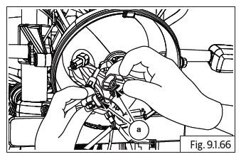
- Gently slide out wiring harness, rubber grommet (a) from the slot in cover LH and remove stator coil along with crank shaft position sensor (b).
Gear Position Sensor
- The gear position sensor (a) is located on the crankcase LH before FD sprocket.
- Ensure Ignition switch and engine stop switch are in OFF position.
- Disconnect wiring coupler (a) of gear position sensor from main wiring harness (b).
- Remove FD sprocket cover.
- Loosen and remove 2 Nos. Hex head bolts (M6) (a) holding the gear position sensor to crankcase LH (b).
- Remove cable bracket (a) and gently pull out gear position sensor from crankcase LH.
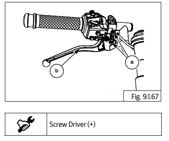
Clutch Switch
- Remove headlamp assembly.
- Disconnect clutch switch connector (a).
- Loosen and remove 2 Nos of screws (a) from clutch lever (b).
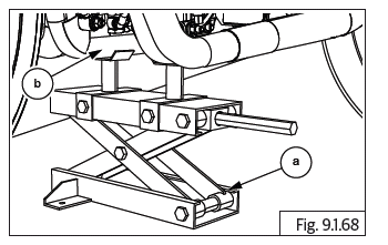
Side Stand Switch
CAUTION Ensure the motorcycle is upright on a firm and flat surface.
- Locate a scissor jack (a) under cradle frame (b) and lift motorcycle such that the front wheel is off the ground by minimum 6 inches (or 15 cm).
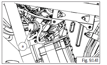
- Disconnect side stand connector (a) from wiring harness located behind engine (b).
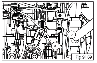
- Release the side stand.
- Loosen and remove Hex socket head cap screw (M5) (a) from side stand switch located on engine frame LH (b).
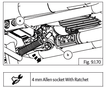
Starter Motor Solenoid
- Remove the following parts:
- Rear wheel.
- Rear mudguard in fill cover.
- Locate solenoid connectors below battery tray, ensure ignition off.
- Disconnect starter solenoid connectors (a) from wiring harness located below battery tray.
- Gently slide and remove solenoid coil (a) from battery tray bracket (b).
See also:
 Royal Enfield Interceptor 650 - Service manual > Engine Management System (EMS)
Engine Management System is responsible for controlling the amount of fuel being injected and for adjusting the ignition timing. Optimum functioning of EMS assures maximum engine power with the lowest amount of exhaust emissions and lowest fuel consumption.
Royal Enfield Interceptor 650 - Service manual > Assembly
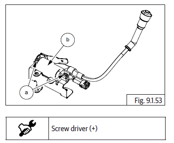
Engine Control Unit (ECU) CAUTION Before assembling any part of the EMS, the Ignition switch and Engine stop switch MUST be in OFF position Before connecting ECU into wiring harness, the battery terminals must be disconnected from the battery. Insert the wiring harness connector (Green point tape) into ECU connector (2) and lock fully closed. Ensure the lock (a) is properly seated. Insert the wiring harness connector ( Yellow point tape ) into ECU connector (1) and lock fully closed. Ensure the lock (a) properly seated.
 Rider's Manual BMW R 1250 GS GSA
 Owner's Manual Harley-Davidson Sportster XL1200X Forty-Eight
 Owner's Manual Honda CBR650R
 Service manual Honda CBR650
 Owner's Manual Honda PCX125
 Owner's Manual Kawasaki Z1000SX
 Service manual Kawasaki Z1000SX
 Owner's Manual Lexmoto Echo
 Owner's Manual Royal Enfield Interceptor 650
 Service manual Royal Enfield Interceptor 650
 Owner's Manual Yamaha MT-07