 Royal Enfield Interceptor 650 - Service manual > Engine Management System (EMS)
Engine Management System is responsible for controlling the amount of fuel being injected and for adjusting the ignition timing. Optimum functioning of EMS assures maximum engine power with the lowest amount of exhaust emissions and lowest fuel consumption.
System Layout
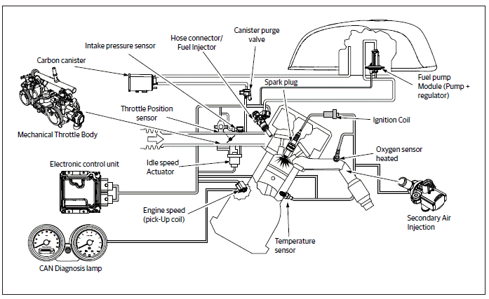
EMS Components
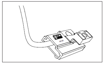
- Electronic Control Unit
- Fuel Injector
- Fuel Supply Module
- Throttle Position Senor
- Manifold Pressure Sensor
- Canister Purge Valve
- HEGO (O2) Sensor
- Idle Air Control Valve
- Secondary Air Injection Solenoid
- Engine Oil Temperature Sensor
- Intake Air Temperature Sensor
- Clutch Switch
- Side Stand Switch
- Gear Position Sensor
- Roll Over Sensor
- Crank Position Sensor
- Starter Motor Relay
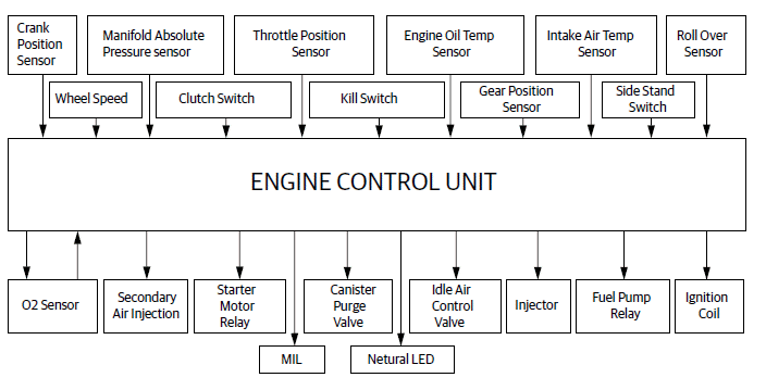
Functional Diagram
Functional Specifications
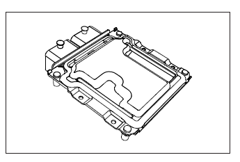
1. Electronic Control Unit (ECU)
Electronic Control Unit is any embedded system that controls one or more electrical system or subsystems in a vehicle.
Engine Control Unit is a type of Electronic Control Unit that controls a series of actuators on an internal combustion engine to ensure optimal engine performance. It does this by reading values from a multitude of sensors within the engine bay, interpreting the data using multidimensional performance maps (called lookup tables), and adjusting the engine actuators accordingly.
Key Elements:
- Micro Controller
- Memory
- Inputs
- Outputs
- Communication Links
Specification:
Operating Voltage: 9 to 16 V
Operating temperature: -40ºC to 70ºC
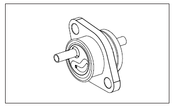
2. Fuel Injectors
Fuel injectors that use pintle valves are operated by electromagnetic components called solenoids. The solenoid is activated, or "pulses" by an ECU which causes it to undergo linear movement.
Since the solenoid is mechanically connected to a pintle valve within the fuel injector, the linear movement causes the pintle to move away from its seat. A small amount of highly pressurized fuel then sprays from the pintle nozzle.
Specification:
Resistance: 12Ω +- 0.6Ω at 22 +- 3ºC
Operating Voltage : 6 to 16 V
Operating Pressure: 350 +- 3.5 kPa
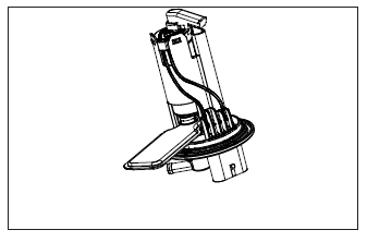
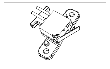
3. Fuel Supply Module
The inlet filter filters the minute dust particles and supplies fuel to the feed pump. The feed pump creates positive pressure in the fuel lines, pushing the gasoline to the injector. The benefit of placing the pump inside the tank is that it is less likely to start a fire. Though electrical components (such as a fuel pump) can spark and ignite fuel vapours, liquid fuel will not explode and therefore submerging the pump in the tank is one of the safest places to mount. The pressure regulator maintains a constant pressure of 350 kpa by returning the surplus fuel back into the tank.
Specification:
Operating Voltage: 8 to 16 V
Fuel Pressure: 350 +- 2 kPa
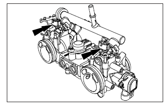
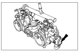
4. Throttle Position Sensor
A Throttle Position Sensor (TPS) is used to monitor the position of the throttle operation and is located on the butterfly spindle so that it can directly monitor the position of the throttle. The sensor is a potentiometer type and therefore provides a variable resistance depending upon the position of the butterfly valve and hence throttle position can be sensed by the ECU. The sensor signal is used by the ECU as an input to its control system. The ignition timing and fuel injection timing (and potentially other parameters) are altered depending upon the position of the throttle, and also depending on the rate of change of the position.
The ECU uses the throttle valve position to know:
- Engine mode: Idle, Part Throttle, Wide-Open Throttle.
- Air-fuel ratio correction.
- Acceleration/ Deceleration correction.
Specification:
Supply Voltage: 5 V
Total Resistance: 2000 +- 600 Ω (Across pins 126 & 207)
Voltage at idle: 0.7 +- 0.35 V
Voltage at WOT: 4.49 to 4.84 V
Note: To see signal, check Voltage across the pins 203 & 207
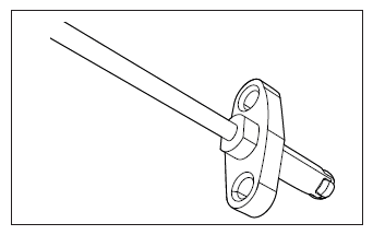
5. Manifold Absolute Pressure Sensor
The Manifold Absolute Pressure sensor provides instantaneous manifold pressure information to the ECU. This is necessary to calculate air density to determine the required fuel metering for optimum combustion and influence the advance or retard of ignition timing.
Specification:
Supply Voltage: 5 V
Pressure Range: 10 to 115 kPa
Temperature Range: -40ºC to 130ºC
Note: To see signal, check Voltage across the pins 112 & 103
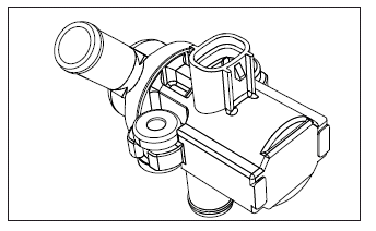
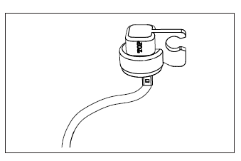
6. Canister Purge Valve
The purge valve is the part of the vehicle Evaporative Emission Control (EVAP) system. The EVAP system prevents fuel vapors in the fuel tank from escaping into the atmosphere. The EVAP system traps fuel vapors from the fuel tank and temporarily stores them in the charcoal canister, see the diagram. When the engine is running under certain conditions, the fuel vapors are purged from the canister and burned inside the engine. The purge valve precisely controls the amount of fuel vapor that is purged from the charcoal canister.
Specification:
Valve: Normally Closed
Resistance: 16 +- 2Ω @ 23 +- 5ºC
7. HEGO Sensor
The Heated Exhaust Gas Oxygen sensor detects the presence of oxygen in the exhaust and produces a variable voltage according to the amount of oxygen detected. The O2 sensor provides feedback to the ECU indicating air/fuel ratio in order to achieve a near stoichiometric air/fuel ratio of 14.7 : 1 during closed loop engine operation. The ideal mixture is the amount of fuel needed to make an engine perform as commanded by the ECU.
The HEGO sensor is a voltage generator which is installed upstream from the catalytic converter. The heated exhaust gas oxygen sensor will generate a voltage signal that is characteristic of this ideal stoichiometric ratio. The HEGO sensor operates as a reference-gas sensor, and compares the residual oxygen in the exhaust gas with the oxygen in the reference atmosphere (air circulating inside the sensor). The active sensor ceramic is heated by the internal heating element; thus sensor heating reduces the influence of the exhaust gas temperature on the sensor-ceramic temperature and therefore the temperature-dependent sensor.
Specification:
Operating Voltage: 16 V (Max)
Operating temperature: 600ºC to 950ºC
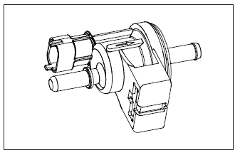
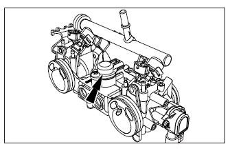
8. Idle Air Control Valve
Idle Air Control Valve is basically a stepper motor controlling the bypass air to the engine and helps to idle and cold start the engine without difficulties. The ECU accordingly collects the data from the engine oil temperature and intake air temperature sensors and operates the stepper motor in regulating the engine RPM. This allows the engine's idle speed to be maintained constant.
Specification:
Operating Voltage: 8 to 16 V
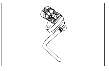
9. Secondary Air Injection Solenoid
Secondary air injection solenoid is used to reduce the tailpipe emissions by burning the unburnt fuel in the exhaust. The solenoid is connected over the top of the air filter box and has a hose leading to the reed valve located in the exhaust port. During the negative pulses in the exhaust, fresh air is drawn into the exhaust stream thereby creating combustion of unburnt gases. The solenoid is controlled by ECU and pulsed when the operating conditions are met.
Specification:
Valve: Normally Open
Resistance: 20 to 24Ω @ 20 to 30ºC
Operating Voltage : 10 to 14.5 V
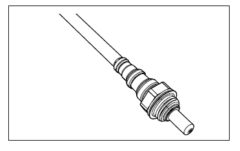
10. Engine Oil Temperature Sensor
Engine oil temperature sensor is thermistor whose resistance is dependent on temperature. It has a Negative Temperature Coefficient where the resistance decreases with increase in temperature. It gives the average temperature of the engine oil to the ECU for making corrections in the injection quantity, ignition timing and for adjusting the stepper opening for better idle stability.
Specification:
Operating Temperature: -55 to 250ºC
Supply Voltage: 5 V
Pin Out Voltage: 2.7734 V @ 39.6ºC (Across Pins 215 & 106)
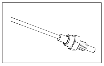
11. Intake Air Temperature Sensor
Intake air temperature sensor is also a Negative Temperature Coefficient sensor where the resistance decreases with increase in temperature. It gives the information about ambient air temperature to the ECU for making corrections in the injection quantity and ignition timing.
Specification:
Operating Temperature: -55 to 125ºC
Supply Voltage: 5 V
Pin Out Voltage:1.777 V @ 39.8ºC (Across Pins 227 & 105)
12. Clutch Switch
Clutch switch gives information to the ECU about the clutch status (i.e) engaged or disengaged with the gearbox.
The clutch switch gives digital input to the ECU (i.e) 0 or 1 which will help in starting of the vehicle when the engine is not in neutral gear.
Specification:
Input Required
13. Side Stand Switch
Side stand switch prevents the vehicle from starting when the side stand is down and not in neutral gear.
Specification:
(Across Pins 226 & 208)
Side stand down: 2.80 to 4.05 V
Side stand up: 0.35 to 1.15 V
14. Gear Position Sensor
Gear Position Sensor indicates the ECU, the gear in which the vehicle is operated at that instant. The input is also required for drive ability calculations in the ECU.
Specification:
(Across Pins 123 & 208)
Neutral gear: 0.37 to 1.16 V
15. Roll Over Sensor
Roll over sensor is also known as bank angle sensor. This sensor gives signal to the ECU if the vehicle rolls off during any mishap or accident. The ECU then cuts off the supply to the fuel injector and the spark plug thus stalling the vehicle, due to which further major mishap is avoided.
Specification:
(Across Pins 225 & 114)
Voltage when vehicle is upright: 0.36 to 1.5 V
Voltage during a fall: 3.75 to 4.35 V
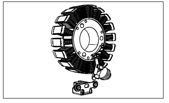
16. Crank Position Sensor
It provides an alternating electrical pulse to the ECU, to determine crankshaft speed and TDC position of the piston in compression stroke. This input will help the ECU to optimize both fuel injection as well as Ignition advance required to suit the crankshaft rotation speed (RPM). In the event throttle is wide open, leading to crankshaft speed above 5500 RPM, the high frequency electrical pulses from the crank position sensor will prompt the ECU to restrict fuel supply so that the crank speed reduces to safe levels. This is a safety aspect to prevent damage to moving engine parts.
Specification:
Output Voltage: 3 - 5 V AC
Resistance : 215Ω +- 10Ω
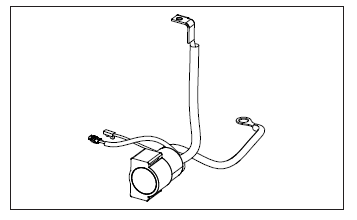
17. Starter Motor Relay
The starter motor is activated by a solenoid, whenever the starter button is depressed to start the engine.
While cranking, when the crank speed attains 600 RPM the ECU commands the starter solenoid to disconnect the power supply to the starter motor so that is will stop spinning.
Also in case the engine does not start within 15 seconds of depressing the starter button, the solenoid will disconnect power supply to the starter motor and will reset to normal condition only after the starter switch is released and after a time delay of about 5 seconds and Crank is at Zero RPM This is a safety feature to safeguard the starter motor, solenoid and the starter clutch.
Specification:
Operating Voltage: 8 to 16 V
See also:
 Royal Enfield Interceptor 650 - Service manual > Brake Bleeding
CAUTION Ensure the motorcycle is upright on a firm and flat surface. Support motorcycle with suitable equipment below cradle frame.
Royal Enfield Interceptor 650 - Service manual > Dismantling
Engine Control Unit (ECU) CAUTION Before disconnecting ECU from the wiring harness, the battery terminals must be disconnected from the battery. Ensure the ignition switch and stop switch are in OFF position. Remove the following: Side panel RH. Side panel LH. Seat from frame. Disconnect battery terminals. ECU is main part of EMS and is located below seat assembly. Loosen and remove 4 Nos. flange Torx head screws (T20) (a) holding ECU (b) to infill cover. Slightly lift up ECU and disconnect fuse box (a) and diagnosis on line (DOL) connector (b) with wiring harness from frame.
 Rider's Manual BMW R 1250 GS GSA
 Owner's Manual Harley-Davidson Sportster XL1200X Forty-Eight
 Owner's Manual Honda CBR650R
 Service manual Honda CBR650
 Owner's Manual Honda PCX125
 Owner's Manual Kawasaki Z1000SX
 Service manual Kawasaki Z1000SX
 Owner's Manual Lexmoto Echo
 Owner's Manual Royal Enfield Interceptor 650
 Service manual Royal Enfield Interceptor 650
 Owner's Manual Yamaha MT-07