 Royal Enfield Interceptor 650 - Service manual > Assembly
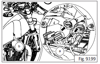
Engine Control Unit (ECU)
CAUTION Before assembling any part of the EMS, the Ignition switch and Engine stop switch MUST be in OFF position Before connecting ECU into wiring harness, the battery terminals must be disconnected from the battery.
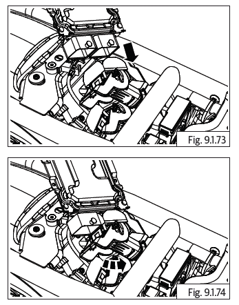
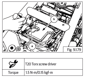
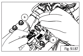
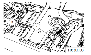
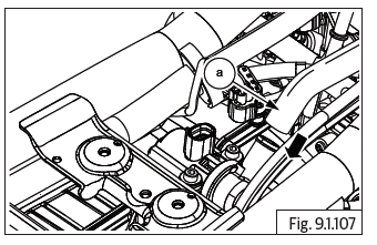
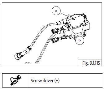
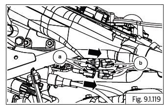
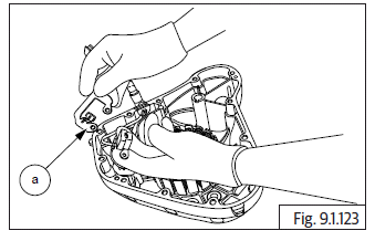
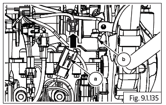
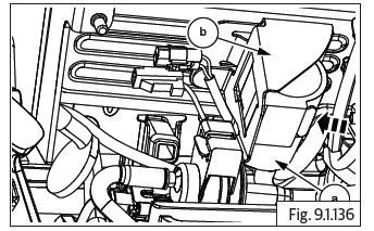
- Insert the wiring harness connector (Green point tape) into ECU connector (2) and lock fully closed.
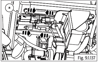
- Ensure the lock (a) is properly seated.
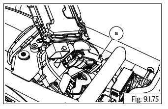
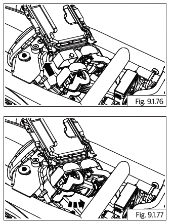
- Insert the wiring harness connector ( Yellow point tape ) into ECU connector (1) and lock fully closed.
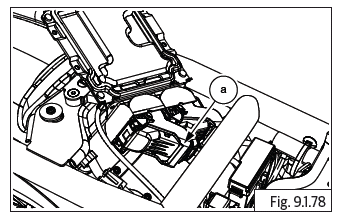
- Ensure the lock (a) properly seated.
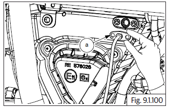
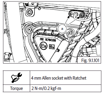
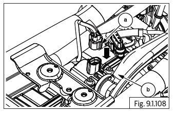
CAUTION Ensure the locks are fully lifted up and released, before connecting wiring connectors into ECU. Insert the wiring harness connector ( Green point tape ) into ECU connector (2) and lock fully closed.
Insert the wiring harness connector ( Yellow point tape ) into ECU connector (1) and lock fully closed.
Ensure the locks are handled with care and do not get damaged or broken Damaged or broken locks will result in loose connections and cause the ECU to fail.
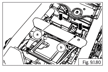
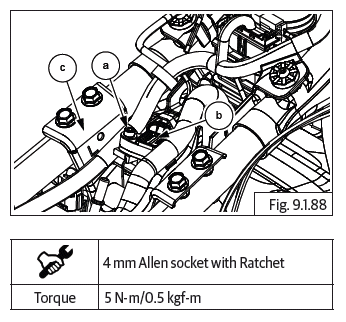
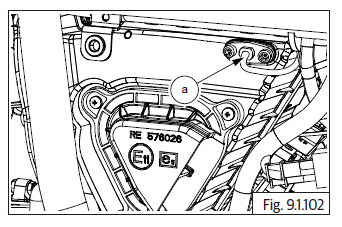
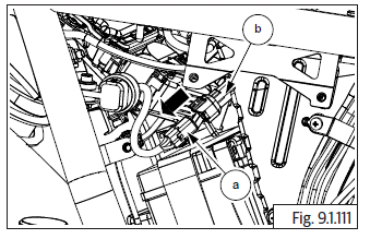
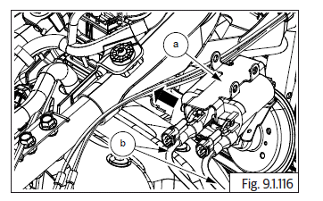
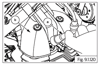
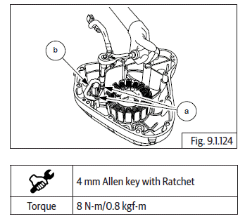
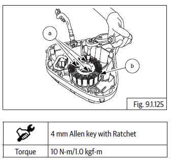
- Locate and tighten 4 Nos. flange Torx head screws (T20) (a) holding ECU (b) to frame.
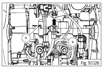
- Locate fuse box (a) and Diagnosis On Line (DOL) connector (b) into frame along with wiring harness.
- Connect battery terminals.
- Assemble rider seat.
- Assemble side panel RH.
Fuel Pump
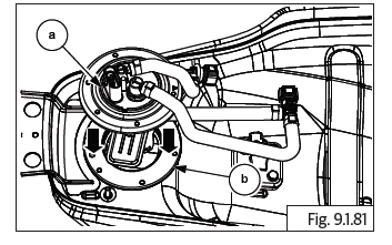
- Ensure Ignition switch and engine stop switch are in ''OFF'' position.
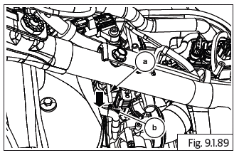
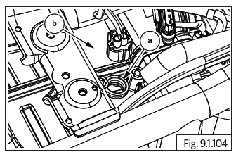
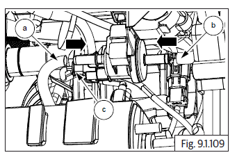
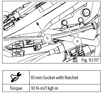
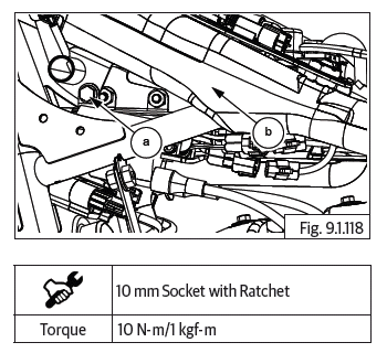
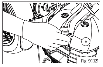
- Gently insert fuel pump (a) from fuel tank (b) along with O-ring.
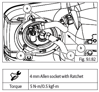
- Locate and tighten 6 Nos. Hex socket head bolts (M5) (a) holding fuel pump (b) to fuel tank (c).
- Assemble fuel tank assembly.
CAUTION Ensure the following: Fuel is refilled into fuel tank. Fuel feed and return hoses are connected into fuel rail.
Wiring couplers to fuel pump and low fuel sensor are connected. EVAP hose pipes are connected.
Water drain hose are connected.
WARNING Gasoline is extremely flammable.
- Assemble rider seat.
- Assemble side panel RH.
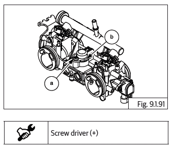
Fuel injectors
- Fuel injectors are located on throttle body along with rail.
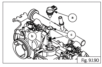
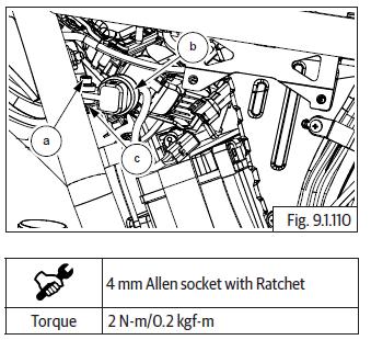
- Ensure the O-rings (a) and (b).
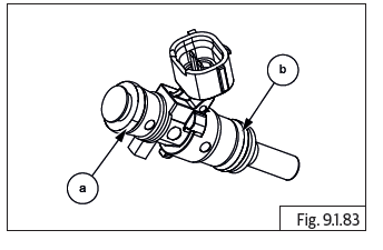
- Gently assemble injectors (a) into fuel rail (b) along with upper and lower O-rings.
- Gently assemble injector lock (c) into fuel rail and injector.
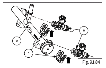
- Gently locate fuel rail (a) along with injectors (b) into throttle body.
- Insert and tighten 2 Nos. button head screws (a) into fuel injector rail (b) located on throttle body.
- Assemble throttle body.
CAUTION Ensure the following: Fuel is refilled into fuel tank. Fuel feed and return hoses are connected into fuel rail.
Wiring couplers to fuel pump and low fuel sensor are connected. EVAP hose pipes are connected.
Water drain hose are connected.
- Assemble the following parts:
- Fuel tank.
- Rider seat.
- RH side cover.
Manifold Absolute Pressure Sensor (MAP)
- Ensure Ignition switch and Engine stop switch are in ''OFF'' position.
- Lock wiring harness connector (a) into MAP sensor connector (b).
- Insert and tighten Hex socket head bolts along with washer (M5) (a) to fix MAP sensor (b) into frame nearest engine steady bracket LH (c).
- Connect MAP Vacuum hose (a) into throttle body (b).
- Assemble fuel tank assembly.
WARNING Gasoline is extremely flammable.
CAUTION Ensure the following: Fuel is refilled into fuel tank.
Fuel feed and return hoses are connected into fuel rail.
Wiring couplers to fuel pump and low fuel sensor are connected. EVAP hose pipes are connected.
Water drain hose are connected.
- Assemble rider seat.
- Assemble side panel RH.
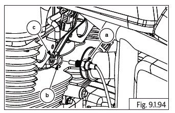
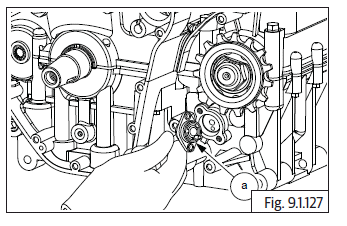
Idle Speed Controller (ISC - Stepper Motor)
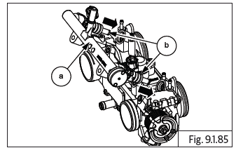
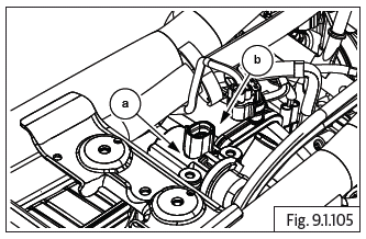
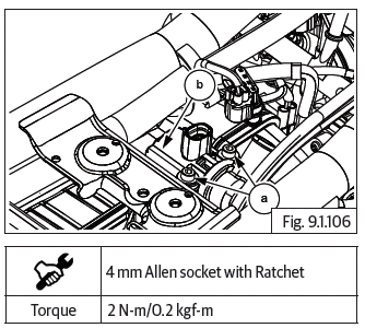
- Locate stepper motor (a) into throttle body (b) along with new O-ring and spring (c).
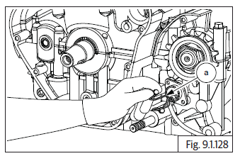
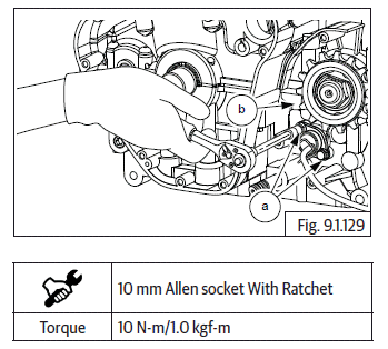
- Insert and tighten button head screw (a) into ISC stepper motor clamp (b).
- Assemble throttle body.
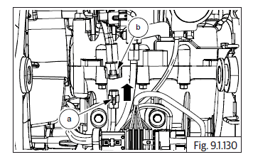
Throttle Body
- Ensure Ignition switch and Engine stop switch are in ''OFF'' position.
NOTE
- Ensure both screws are sufficiently loosened and the worm clips rotates easily in the groove in the manifolds.
- Ensure both screws are sufficiently loosened, and the worm clips rotates easily in the groove in the air filter bellows worm clips.
- Gently locate throttle body into inlet manifold rubbers with fuel rail and injectors and ISC/TPS.
- Tighten worm clip screw on inlet manifold on Cylinder (RH).
- Tighten worm clip screw on inlet manifold on Cylinder (LH).
- Tighten wire clips on the LH and RH air filter connection tubes.
- Tighten the 2 Nos. air filter box assembly mounting bolts.
- Insert MAP sensor vacuum hose into throttle body.
- Insert EVAP hoses into throttle body.
- Connect electrical couplers into TPS, idle speed control stepper motor and Fuel injectors LH and RH.
- Assemble the following:
- Throttle cable.
- Throttle body covers LH and RH.
- Fuel tank assembly.
CAUTION Ensure the following: Fuel is refilled into fuel tank. Fuel feed and return hoses are connected into fuel rail.
Wiring couplers to fuel pump and low fuel sensor are connected. EVAP hose pipes are connected.
Water drain hose are connected.
WARNING Gasoline is extremely flammable.
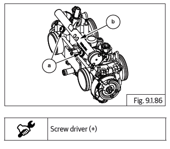
Throttle Position sensor (TPS)
- The TPS (a) is located on the left side of the throttle body and should NOT BE REMOVED from the throttle body under any circumstances.
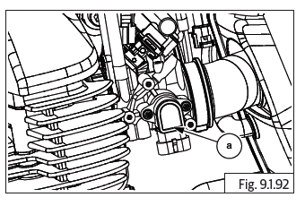
Engine Oil Temperature Sensor (EOT)
- The EOT (a) is located on the LH side cylinder head below the throttle body.
- Locate EOT sensor (a) along with O-ring (b) into engine head assembly (c).
- Tighten EOT sensor Hex head (M17) (a) into engine head assembly (b).
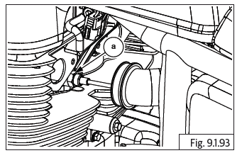
- Connect EOT sensor connector (a) into wiring harness (b) above throttle body.
- Ensure connector is locked and wire is routed correctly.
- Assemble throttle body cover LH.
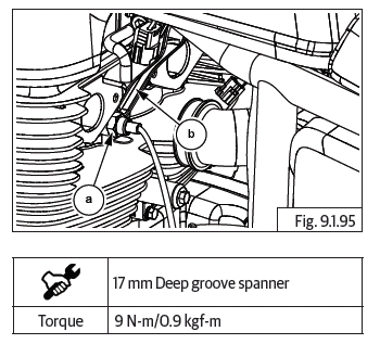
HEGO (O2) Sensors
- The HEGO sensors are located on the exhaust pipes near the cylinder head.
WARNING The engine and exhaust systems get extremely hot during normal operation and can result in serious burns if touched. Make sure exhaust pipes are not hot and is at the same levels of ambient/surrounding temperature, whenever working on the engine or exhaust systems.
NOTE
- Ensure the engine/exhaust is cold before assembling the HEGO (O2) sensors.
- Ensure Ignition switch and Engine stop switch are in OFF position.
- Insert the RH HEGO (O2) sensor wiring coupler through a deep grooved ring spanner on the sensor hex head tighten HEGO sensor RH (a) into exhaust pipe RH (b).
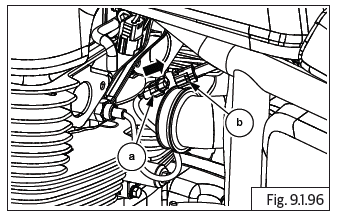
- Insert the LH HEGO (O2) sensor wiring coupler through a deep grooved ring spanner on the sensor hex head tighten HEGO sensor LH (a) into exhaust pipe LH (b).
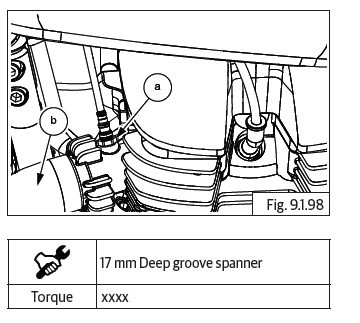
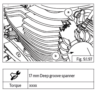
- Connect HEGO sensor connectors (a) from wiring harness located near ignition coil assembly below fuel tank (b).
- Assemble LH and RH horn assembly.
Intake Air Temperature sensor (IAT)
- Gently locate IAT sensor (a) into air filter housing.
- Insert and tighten 2 Nos. Hex socket head cap screw (M5) (a) into IAT sensor (b).
- Ensure IAT sensor (a) seated properly.
- Connect IAT sensor connector (a) on the air filter housing (b) and ensure locked properly.
- Assemble the following parts:
- Side panel LH.
- Rider seat.
- Side panel RH.
Secondary Air Injection Unit (Solenoid) Air Cut Valve (ACV)
- Ensure Ignition switch and Engine stop switch are in OFF position.
- The ACV is assembled on the top RH side of the air filter housing.
- Ensure grommet (a) into air filter (b).
- Assemble ACV (a) into grommet in air filter (b).
- Locate and tighten 2 Nos. Hex socket head cap screws (M5) (a) along with washer into ACV (b) on air filter.
- Insert hose (a) into ACV.
- Connect wiring harness connector (a) into ACV (b).
- Assemble fuel tank assembly.
CAUTION Ensure the following: Fuel is refilled into fuel tank. Fuel feed and return hoses are connected into fuel rail.
Wiring couplers to fuel pump and low fuel sensor are connected. EVAP hose pipes are connected.
Water drain hoses are connected.
WARNING Gasoline is extremely flammable and highly explosive. Please handle with care. Improper handling can lead to fatal accident or serious injury. Always drain/fill fuel only in a well ventilated area. Ensure there is no scope for flames or sparks near by while draining/filling fuel.
- Assemble the following parts:
- Side panel LH.
- Rider seat.
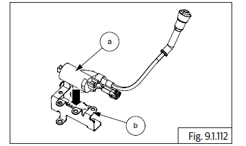
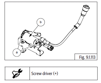
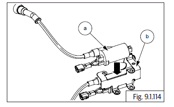
Purge Valve
- Locate and install EVAP purge control valve into bracket under the battery tray.
- Connect the inlet (a) and outlet (b) hoses to EVAP purge control valve.
- Connect the electrical connector (c) to EVAP purge control valve.
- Assembly the following parts:
- Connect roll over sensor connector.
- Infill mudguard.
- Rear mudguard.
- Engine control unit (ECU).
- Side panel LH.
- Rider seat.
- Side panel RH.
Roll Over Sensor
- The Roll over sensor is located on the frame RH side above battery.
- Locate and tighten Hex socket head cap screw (M5) (a) roll over sensor (b) into frame (c).
- Connect roll over sensor connector (a) to wiring harness connector (b) located above battery RH.
- Assemble the following parts:
- Rider seat.
- Side panel RH.
Ignition Coil
- Assemble ignition coil RH (a) into bracket (b).
- Insert and tighten 2 Nos. slot head round screws (M5) (a) into ignition coil RH (b).
- Assemble ignition coil LH (a) into bracket (b).
- Insert and tighten 2 Nos. slot head round screws (M5) (a) into ignition coil RH (b).
- Locate ignition coil assembly (a) along with HT cables (b).
- Locate and tighten 2 Nos. Hex head collar bolt (M6) (a) into main frame RH (b).
- Locate and tighten Hex head collar bolt (M6) (a) into main frame LH (b).
- Connect ignition coil connector LH and RH (a) from wiring harness (b) located below fuel tank.
- Gently insert HT cable RH (a) into spark plug (b).
- Gently insert HT cable LH (a) into spark plug.
- Assemble fuel tank.
CAUTION Ensure the following: Fuel is refill into fuel tank. Fuel feed and return hoses are connected into fuel rail.
Wiring couplers to fuel pump and low fuel sensor are connected. EVAP hose pipes are connected.
Water drain hose are connected.
WARNING Gasoline is extremely flammable.
- Assemble rider seat Assembly.
- Assemble side panel RH.
Crank Position Sensor
- The crank position sensor is located inside the engine cover LH and attached to the stator coil.
- Locate starter coil along with crank shaft position sensor wire assembly (a) into cover LH (b).
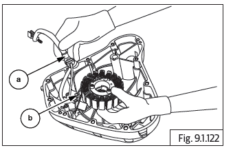
- Assemble guide plate (a) into LH cover.
- Locket and tighten 2 Nos Hex socket head screws (M5) (a) into guide plate (b).
- Locate and tighten 3 Nos. Hex socket head screws (M5) (a) into LH cover that hold starter coil (b).
- Locate crank shaft position sensor and wiring harness behind engine on RH, near RR module.
- Connect crank position sensor connector (a) to harness connector (b).
- Ensure the wiring harness strapped properly.
- Assemble the following parts:
- FD sprocket cover.
- Cover LH from Engine Refer.
- Fill engine oil.
Gear Position Sensor
- The gear position sensor is located on the crankcase LH before FD sprocket
- Ensure Ignition switch and Engine stop switch are in OFF position.
- Gently locate gear position sensor (a) below FD sprocket.
- Gently locate gear position sensor wiring holder over gear position sensor and locate the bracket (a).
- Insert and tighten 2 Nos. Hex head bolts (M6) (a) located below FD sprocket.
- Connect gear position sensor connector (a) to wiring harness connector located on rear side of engine (b).
- Ensure connector is locked properly and wiring is routed correctly.
- Assemble FD sprocket cover.
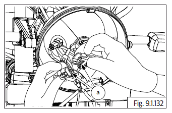
Clutch Switch
- Locate and tighten 2 Nos of screws (a) into clutch lever (b).
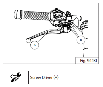
- Connect connectors (a) into clutch switch on handlebar LH (b).
- Assemble headlamp assembly.
Side Stand Switch
CAUTION Ensure the motorcycle is upright on a firm and flat surface.
- Locate a scissor jack (a) under cradle frame (b) and lift motorcycle such that the front wheel is off the ground by minimum 6 inches (or 15 cm).
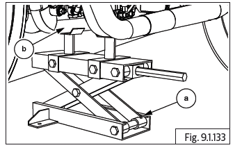
- Ensure side stand is released.
- Locate and tighten Hex socket head cap screw (M6) (a) into side stand switch located on engine frame LH (b).
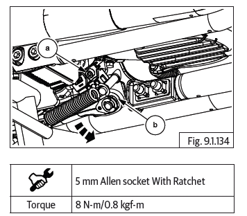
- Connect side stand connector (a) into wiring harness connector located behind engine frame RH (b).
- Ensure connectors are locked properly and routed correctly.
Starter Motor Solenoid
- Locate solenoid connectors below battery tray Ensure ignition off.
- Gently slide and locate solenoid coil (a) into battery tray bracket (b).
- Connect starter solenoid connectors (a) into wiring harness.
- Assemble the following:
- Rear mudguard in fill cover.
- Wheel speed sensor front and rear.
Actuator
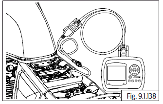
Actuator Tests
- The following actuators can be tested for their functionality using the
diagnostic tool/ PC software.
- Fuel Pump
- Injector
- Ignition Coil
- O2 sensor heater
- Malfunction Indication Lamp (MIL)
- Idle Air Control Valve (IACV)
- Canister Purge Valve (CPV)
- Secondary Air Injection Solenoid (SAI)
- Accessory Relay
Test Procedure
- Entry Conditions
- Actuator tests can be carried out when the ignition key and kill switch are ON and engine speed is 0.
- For IACV alone, engine speed can be greater than 0.
- For actuation of injector and ignition coil, gear should be in neutral. If not in neutral, clutch lever should be pressed.
- Errors associated to the corresponding actuator, if present, will inhibit the actuation.
- Procedure
- In EOL software
- Connect the tool with the diagnostic coupler in the vehicle and connect it with PC using the USB cable.
- Select the option "EOL" & select Actuator.
- Select the required actuator and press.

- In NACSII tool
- Connect the tool with the diagnostic coupler in the vehicle
- In EOL software
- Select the vehicle model name and select Bosch Engine Management System
- Select the option Actuator
- Select the required actuator and press F3 to actuate
- Method of verification
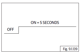
1. For fuel pump, when actuated, an audible sound can be heard for 5 seconds.
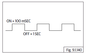
2. Prior to actuation of injector, prime the fuel pump 3 times to build up sufficient pressure in fuel line. To ensure injectors are working properly, remove the throttle body from the intake manifold, connect all the injector couplers and actuate. When actuated, 3 pulses of fuel spray from the injector can be seen. Each injector can be actuated and checked individually
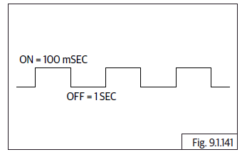
3. Prior to the actuation of ignition coil, remove the suppressor cap and connect with an external spark plug and ground it to engine. Do not ground the ignition coil directly. When actuated, 3 sparks can be seen. Each ignition can be actuated and checked individually.
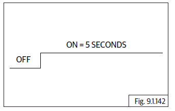
4. To check O2 sensor heater, the sensor has to be removed from the exhaust pipe. When actuation is requested, the sensor will get heated up and this happens for 5 seconds.
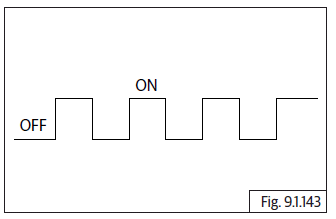
5. When MIL is actuated, the bulb goes ON & OFF for 5 times.
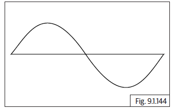
6. Start and idle the engine before actuating IACV. If actuation command is given, one can observe the engine rpm rising up & falling down the target idle speed. Once actuation is completed, it settles back to target idle speed.
7. When CPV is actuated, a pulsating sound can be observed. If not, the canister purge valve has to be manually touched to feel actuation.
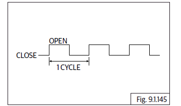
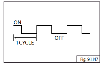
8. SAI solenoid will get actuated for 20 cycles.
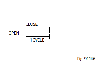
9. Accessory relay gets actuated for 5 cycles.
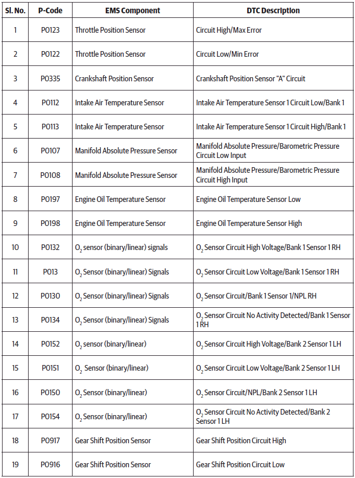
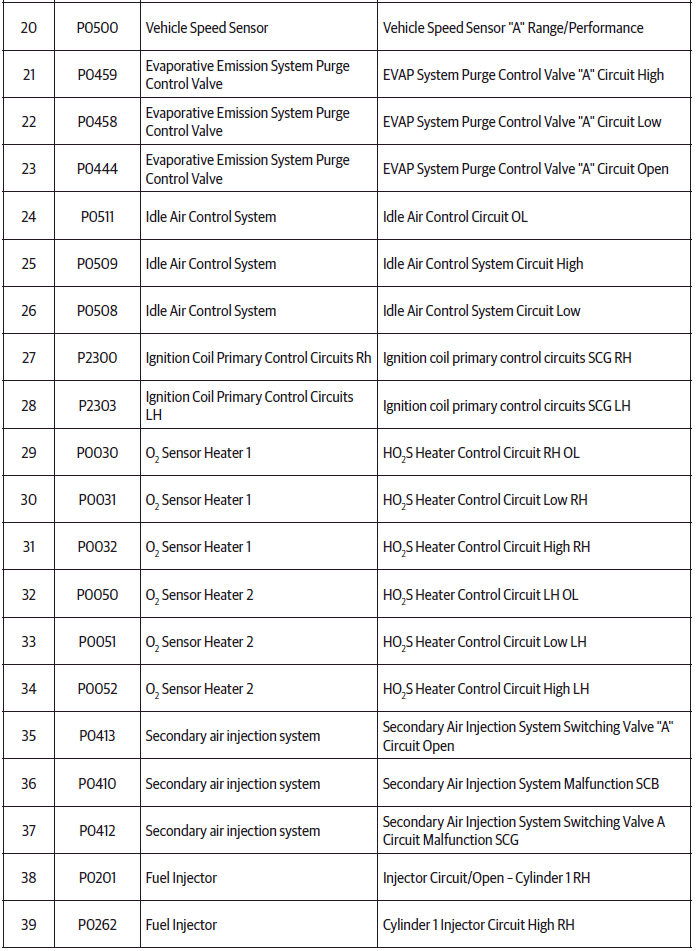
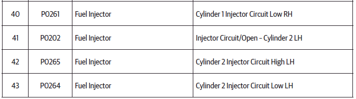
EMS DTC Codes
See also:
 Royal Enfield Interceptor 650 - Service manual > Dismantling
Engine Control Unit (ECU) CAUTION Before disconnecting ECU from the wiring harness, the battery terminals must be disconnected from the battery. Ensure the ignition switch and stop switch are in OFF position. Remove the following: Side panel RH. Side panel LH. Seat from frame. Disconnect battery terminals. ECU is main part of EMS and is located below seat assembly. Loosen and remove 4 Nos. flange Torx head screws (T20) (a) holding ECU (b) to infill cover. Slightly lift up ECU and disconnect fuse box (a) and diagnosis on line (DOL) connector (b) with wiring harness from frame.
Royal Enfield Interceptor 650 - Service manual > Electrical System
Electrical System Components - Front
 Rider's Manual BMW R 1250 GS GSA
 Owner's Manual Harley-Davidson Sportster XL1200X Forty-Eight
 Owner's Manual Honda CBR650R
 Service manual Honda CBR650
 Owner's Manual Honda PCX125
 Owner's Manual Kawasaki Z1000SX
 Service manual Kawasaki Z1000SX
 Owner's Manual Lexmoto Echo
 Owner's Manual Royal Enfield Interceptor 650
 Service manual Royal Enfield Interceptor 650
 Owner's Manual Yamaha MT-07