 Royal Enfield Interceptor 650 - Service manual > Electrical System
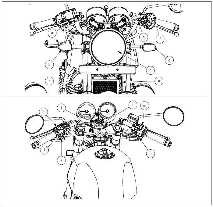
Electrical System Components - Front
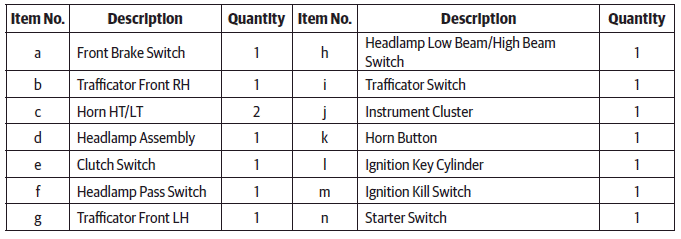
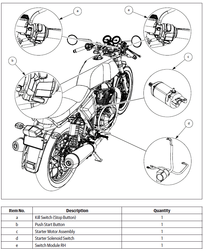
Electrical System Components - Rear
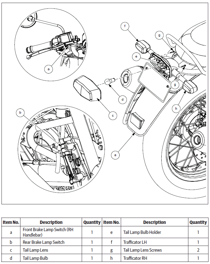
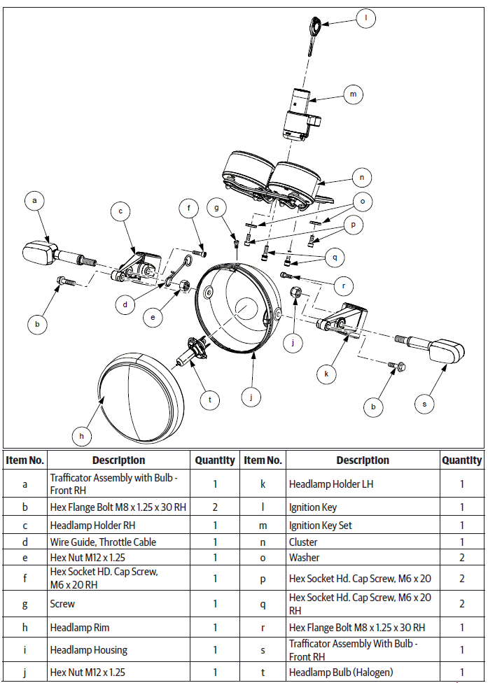
Headlamp and Cluster
Charging System
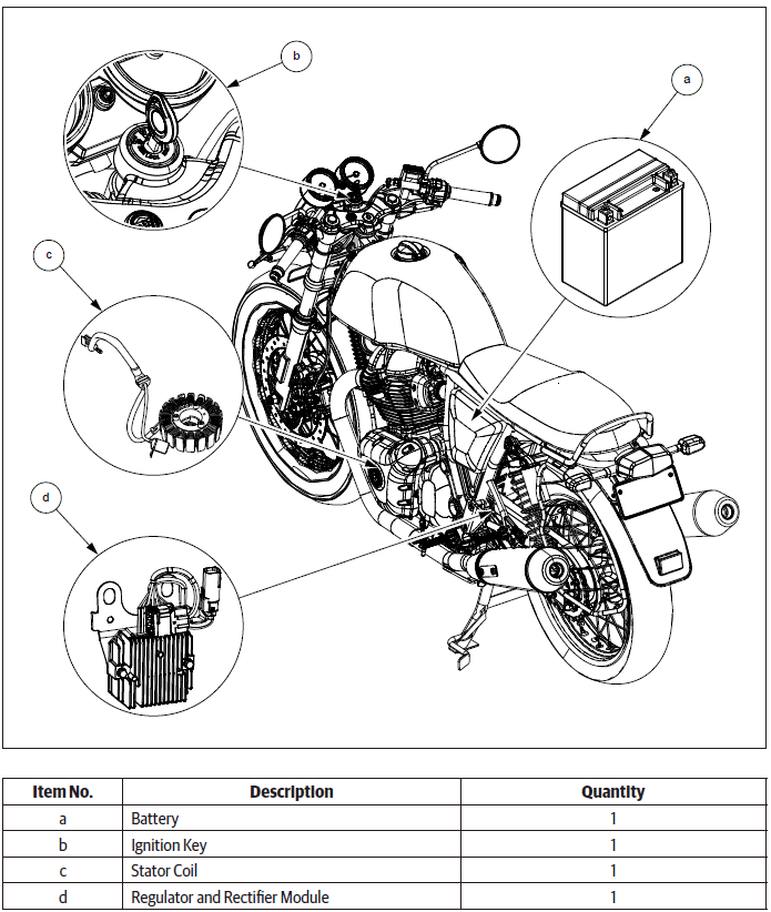
Charging System
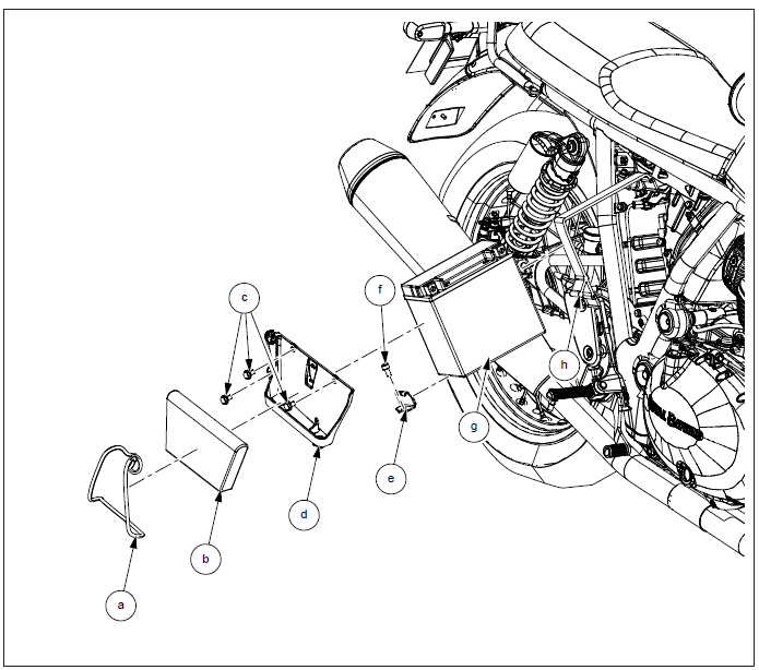
Battery
- Headlamp and Cluster Dismantling
- Trafficators Dismantling
- Battery Dismantling
- Horn Dismantling/Assembly
- Battery Assembly
- Trafficators Assembly
- Brake Lamp Connectors Assembly
- Headlamp and Cluster Assembly
See also:
 Royal Enfield Interceptor 650 - Service manual > Assembly
Engine Control Unit (ECU) CAUTION Before assembling any part of the EMS, the Ignition switch and Engine stop switch MUST be in OFF position Before connecting ECU into wiring harness, the battery terminals must be disconnected from the battery. Insert the wiring harness connector (Green point tape) into ECU connector (2) and lock fully closed. Ensure the lock (a) is properly seated. Insert the wiring harness connector ( Yellow point tape ) into ECU connector (1) and lock fully closed. Ensure the lock (a) properly seated.
Royal Enfield Interceptor 650 - Service manual > Headlamp and Cluster Dismantling
Headlamp Reflector from Housing NOTE Ensure ignition switch and stop switch in off condition CAUTION Support the Headlamp assembly carefully. Loosen and remove Phillips screw (a) on headlamp. Gently remove front rim (a) along with reflector (b) from housing (c).
 Rider's Manual BMW R 1250 GS GSA
 Owner's Manual Harley-Davidson Sportster XL1200X Forty-Eight
 Owner's Manual Honda CBR650R
 Service manual Honda CBR650
 Owner's Manual Honda PCX125
 Owner's Manual Kawasaki Z1000SX
 Service manual Kawasaki Z1000SX
 Owner's Manual Lexmoto Echo
 Owner's Manual Royal Enfield Interceptor 650
 Service manual Royal Enfield Interceptor 650
 Owner's Manual Yamaha MT-07