 Royal Enfield Interceptor 650 - Service manual > Headlamp and Cluster Assembly
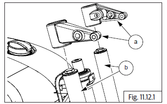
Headlamp Housing Holders into Fork Legs
- Assemble LH & RH headlamp housing holders (a) into front fork legs LH & RH (b).
- Hold headlamp holders with 58 mm of distance from the steering stem top face.
- Assemble handlebar clip-on LH and RH.
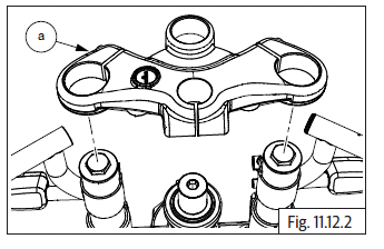
- Assemble upper yoke (a) into steering stem.
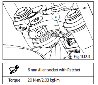
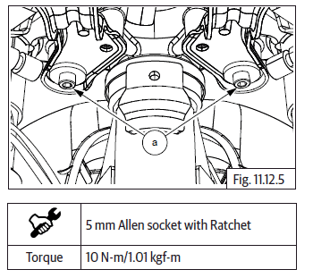
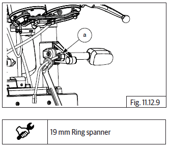
- Insert and tighten Hex socket head bolt (M8) (a) on top yoke RH.
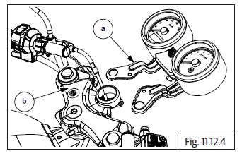
Cluster Assembly
- Insert cluster bracket (a) into upper yoke (b).
- Insert and tighten 2 Nos. Hex socket head bolts (M6) (a) into LH and RH of cluster bracket.
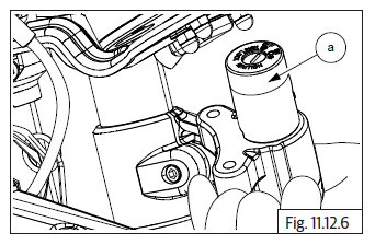
- Locate ignition key set (a) into cluster bracket.
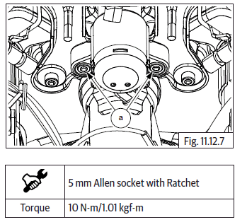
- Insert and tighten 2 Nos. Hex socket head bolts (M6) (a) into LH & RH of key set.
- Connect cluster connection.
Direction Trafficators into Headlamp Holder
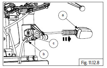
- Assemble LH direction trafficator (a) along with nut (b) washer (c) into headlamp holder. Similarly assemble RH direction trafficator.
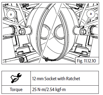
- Insert and tighten Hex nut (M12) (a) to fix LH & RH direction trafficators.
Headlamp Housing into Holder LH & RH
- Locate headlamp housing into holder and insert and tighten Hex flange holder bolts (M8) (a) on LH & RH housing.
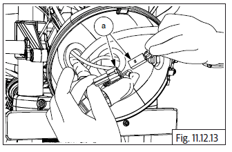
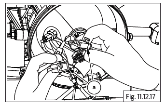
Connectors and Sensors into Headlamp Housing
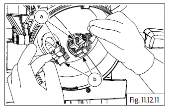
- Locate and connect cluster connectors (a) and (b). Ensure it is properly seated/locked.
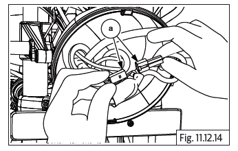
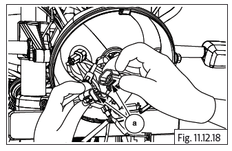
- Locate and connect ignition switch connector (a). Ensure it is properly seated/locked.
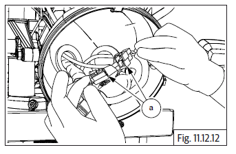
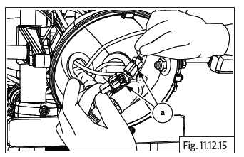
- Locate and connect RH trafficator sensor connector (a). Ensure it is properly seated/locked.
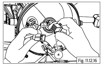
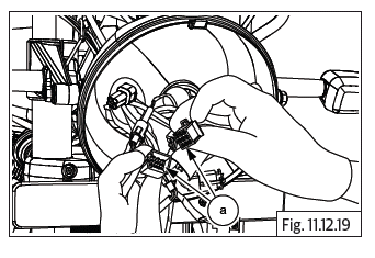
- Depress and lock LH trafficator sensor connector (a). Ensure it is properly seated/locked.
- Locate and connect wheel speed sensor connector (a). Ensure it is properly seated/locked.
- Locate and connect RH module connector (a). Ensure it is properly seated/locked.
- Connect front brake lamp switch connector (a). Ensure it is properly seated/locked.
- Connect clutch switch connector (a). Ensure it is properly seated/locked.
- Locate and connect LH module connector (a) into headlamp housing. Ensure it is properly seated/ locked.
Headlamp Bulb into Reflector
CAUTION Do not touch glass of bulb. Any strains or finger prints will affect the luminosity. Ensure pointed tip of bulb does not get damaged Whenever handling the bulb, hold it firmly at terminal end and not at glass end.
- Gently locate headlamp bulb (a) into reflector and install wire clip (b) onto reflector (c).
- Depress wire clip (a) and lock into slot (b) in headlamp reflector.
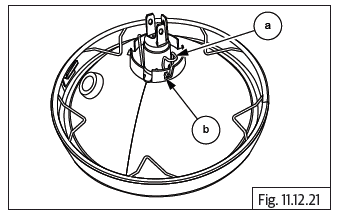
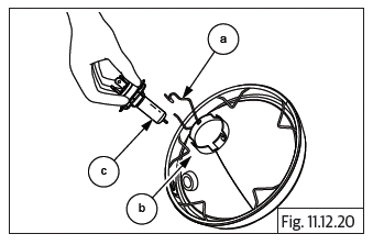
Pilot Bulb into Reflector
- Gently depress bulb (a) to holder and turn clockwise to fix bulb into holder (b).
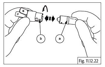
Headlamp Reflector into Housing
- Gently assemble pilot bulb (a) along with holder (b) into headlamp reflector.
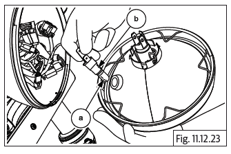
- Connect wires (a) into pilot bulb main (b) and ground (c) carefully.
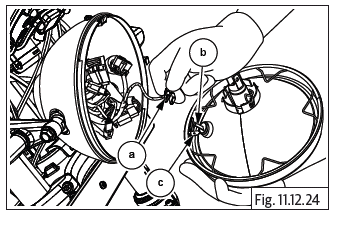
- Hold headlamp carefully and connect headlamp connector (a) into headlamp bulb.
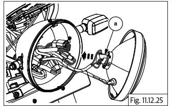
CAUTION Support the headlamp assembly properly and carefully.
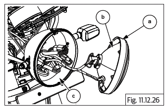
- Carefully assemble reflector (b) along with front rim (a) into housing (c).
- Insert and tighten Phillips screw (a) on headlamp.
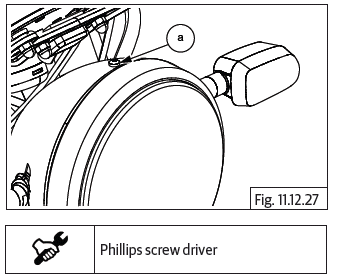
- Inspect and test all electrical functions after completing assembly.
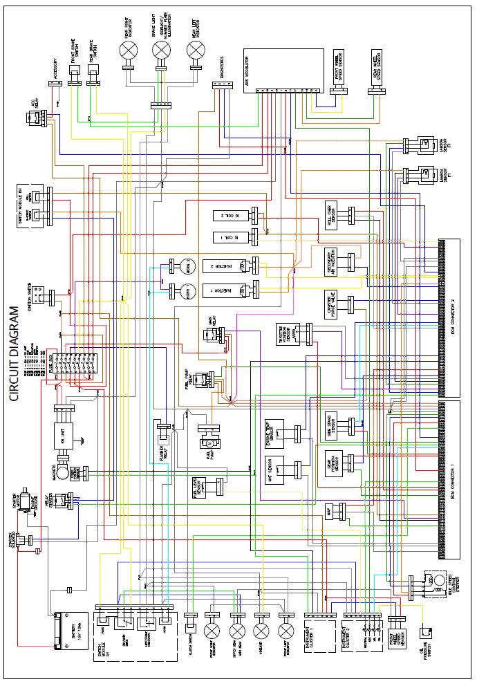
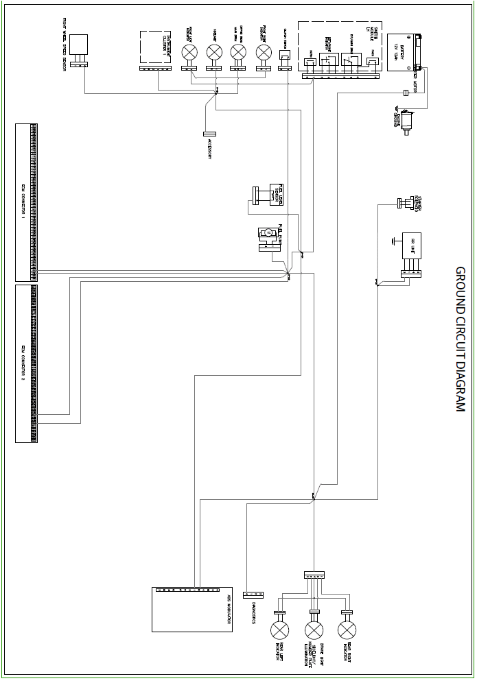
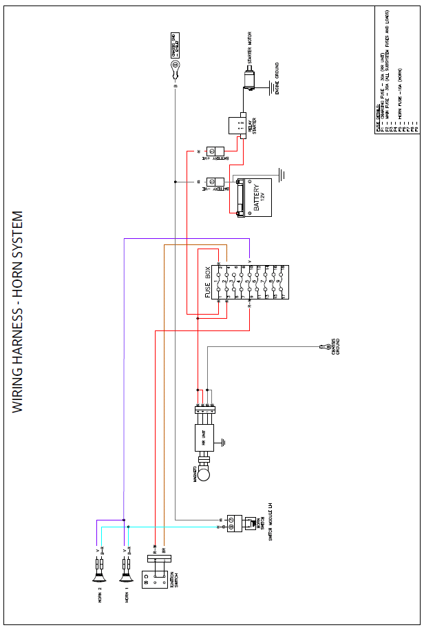
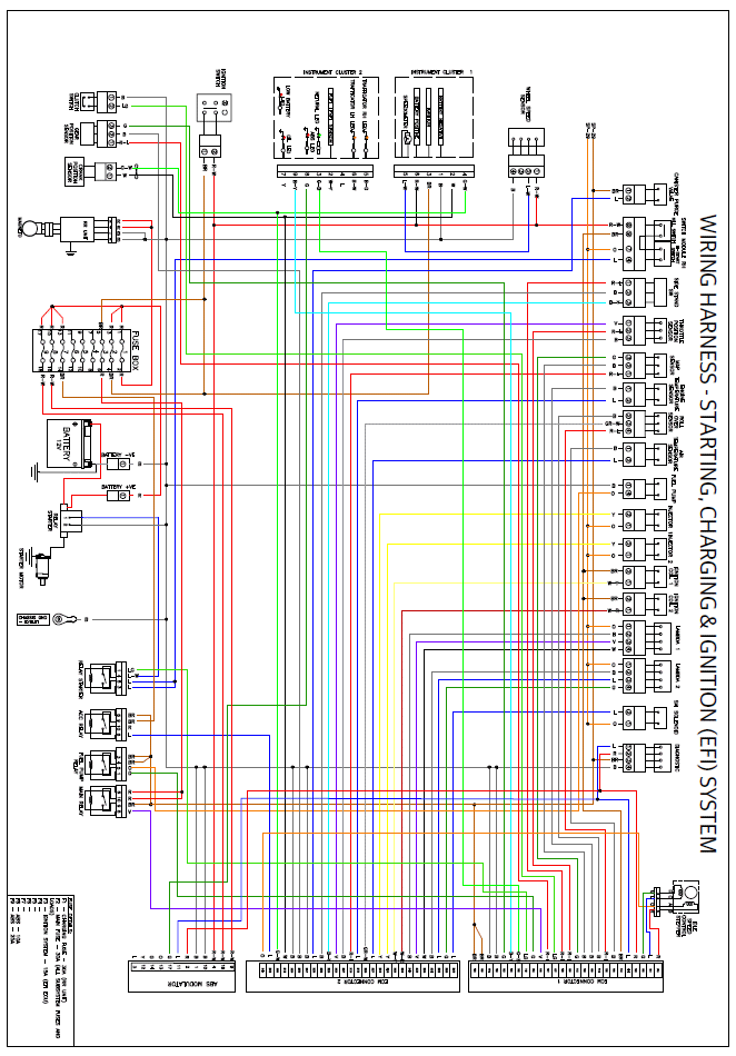
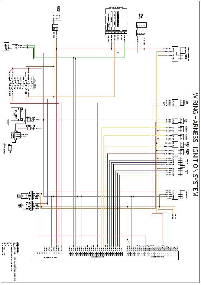
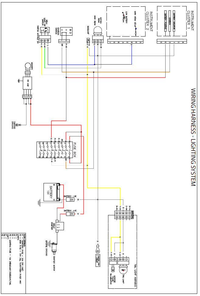
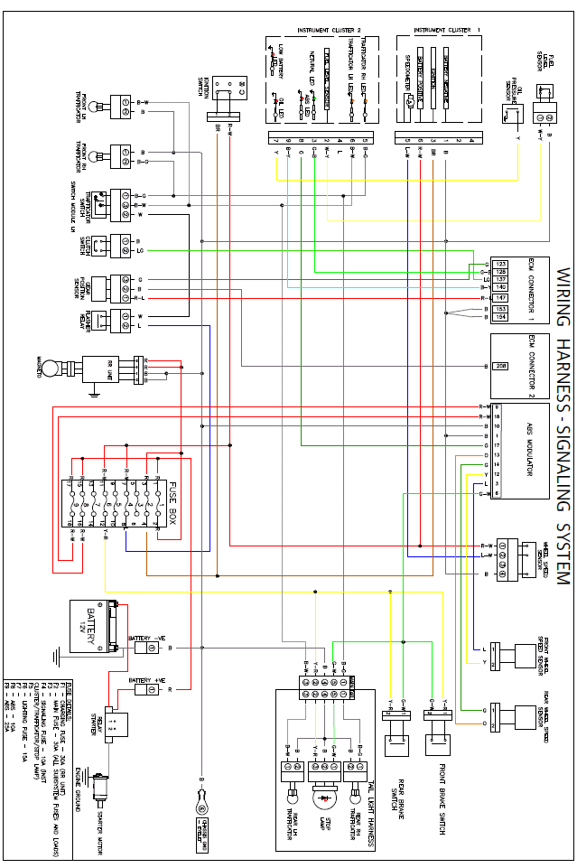
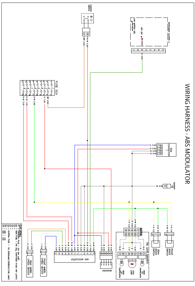
Wiring Diagram
Main Wiring Harness
Ground Circuit Diagram
Horn System
Starting, Charging and Ignition System
Ignition System
Lighting System
Signaling System
ABS
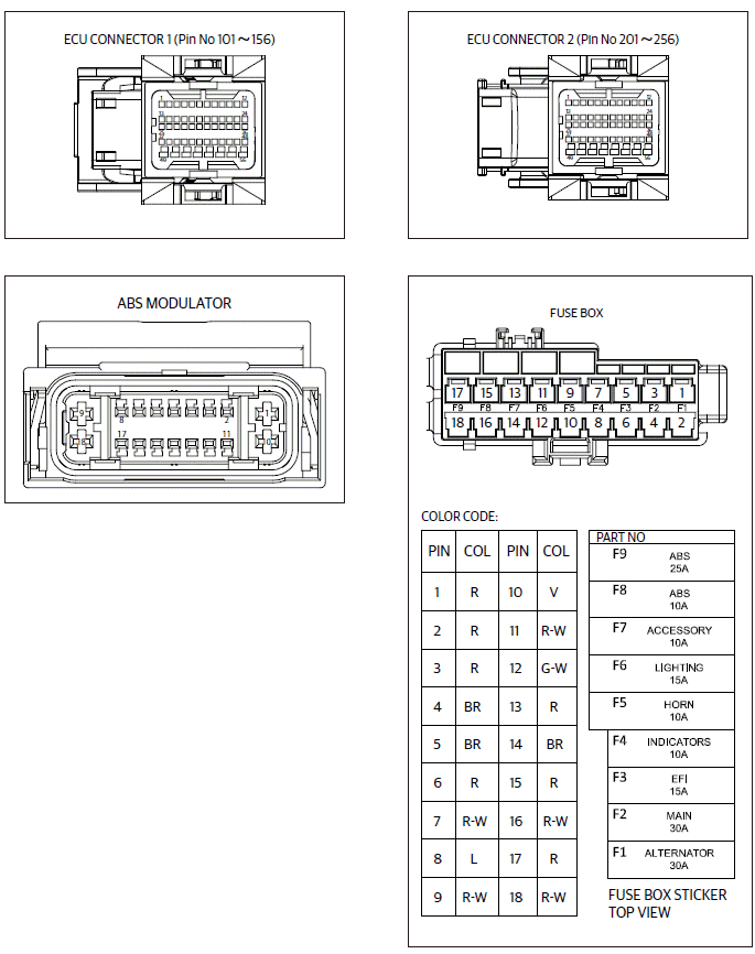
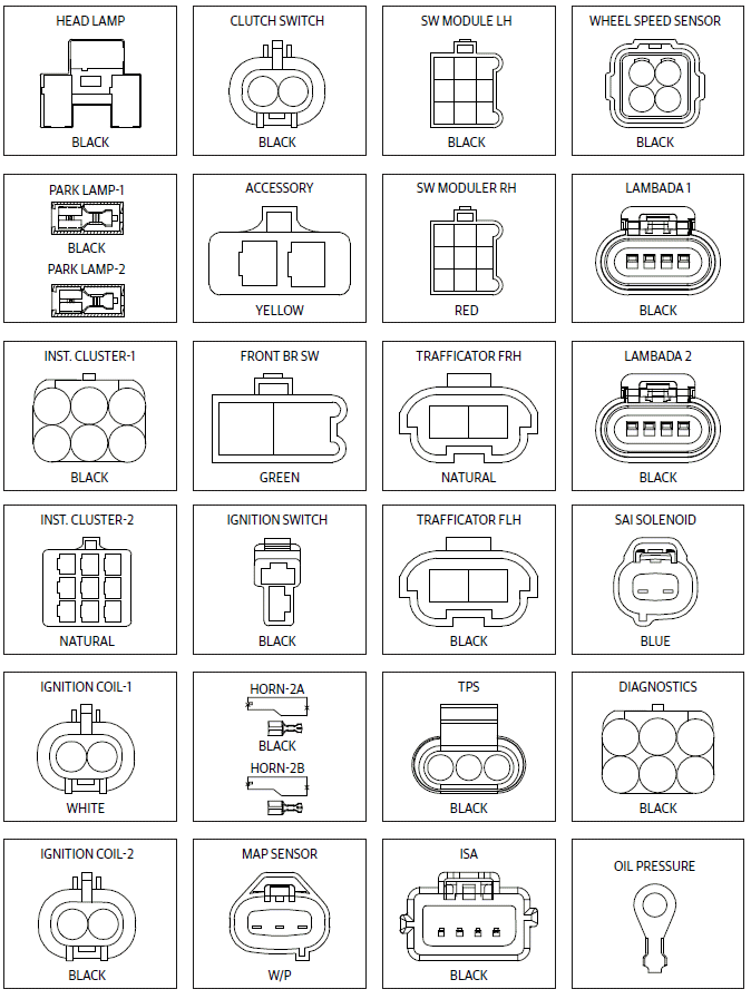
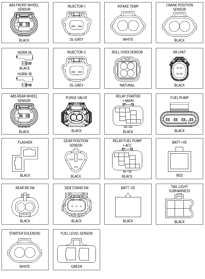
Connectors Layout
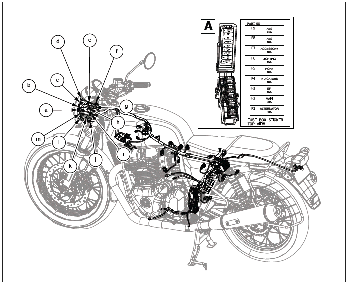
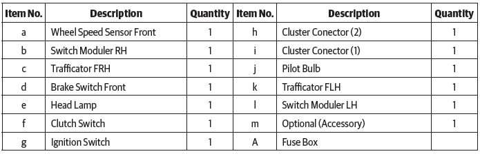
Connectors Layout
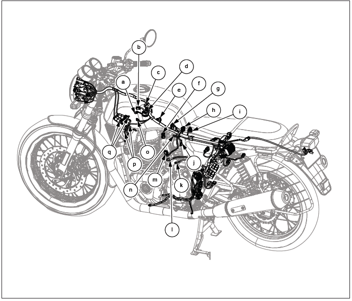
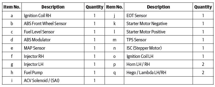
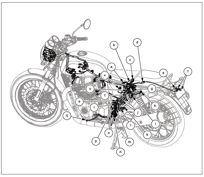
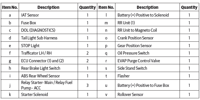
Connectors
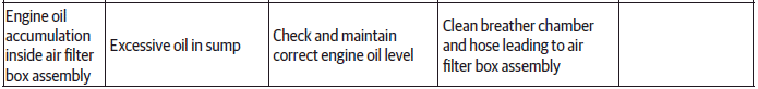
Troubleshooting
Air Filter
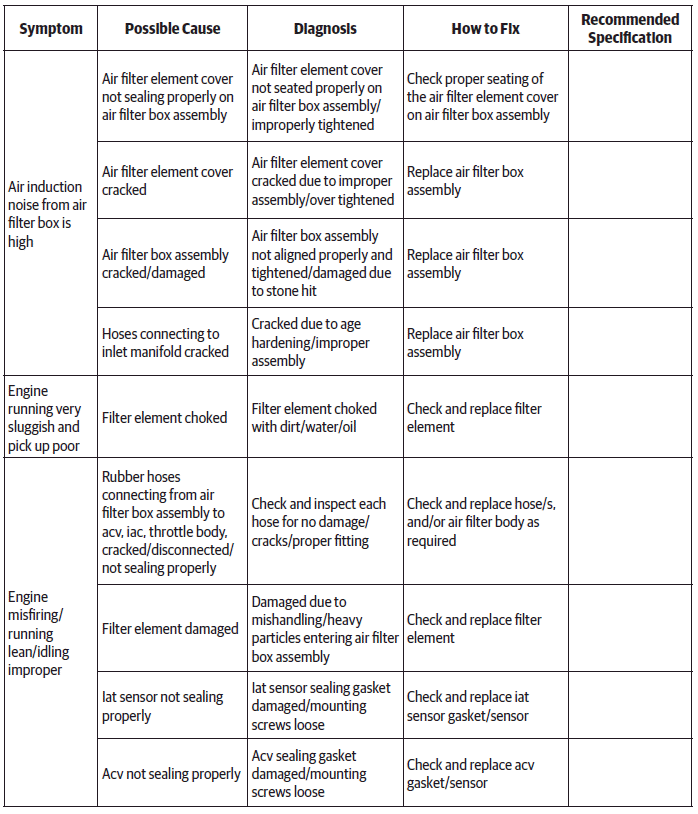
NOTE
- The trouble shooting given in this section is only related to issues with air filter. For complaints like sluggish running/misfiring improper idling etc., it will also be necessary to check the other aspects such as fuel, ignition, EMS, battery conditions etc., and correct.
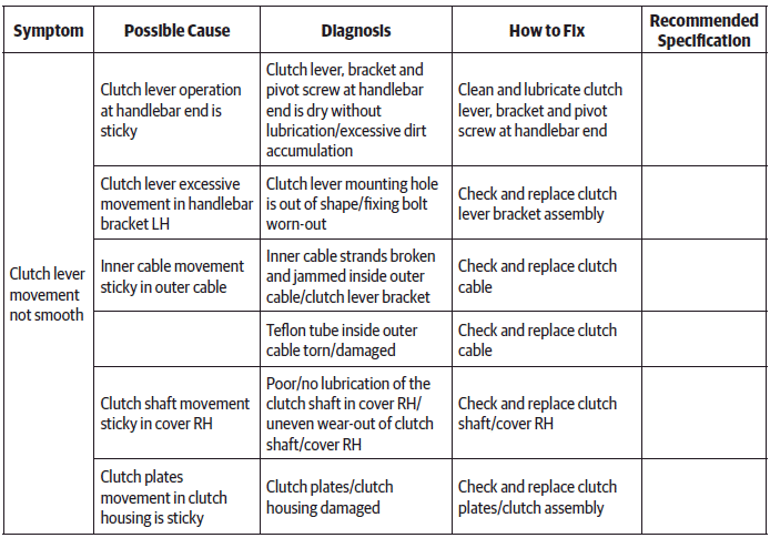
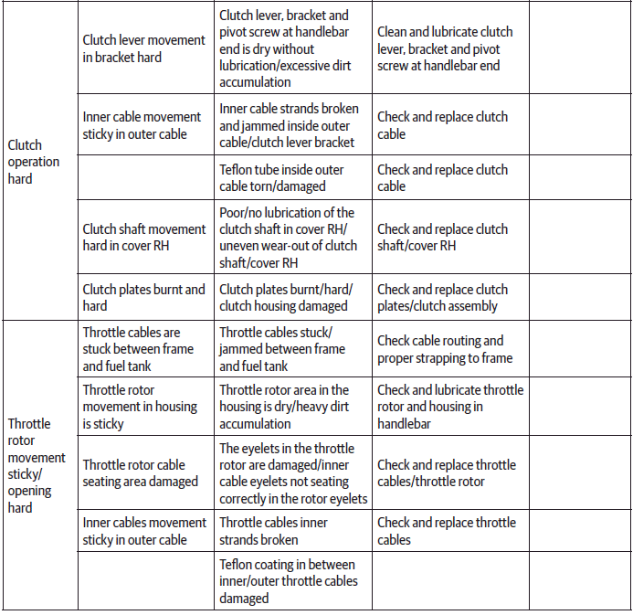
Control Cables
Handlebar
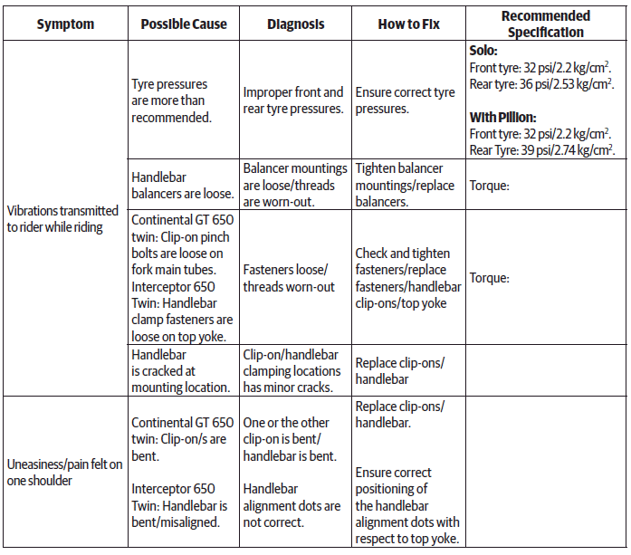
NOTE
- The troubleshooting given in this section is only related to issues with Handlebar. For complaints like unstable riding, wobbling, etc., it will be necessary to check other aggregates like wheel, front/rear suspension and so on.
Exhaust Pipes and Silencers
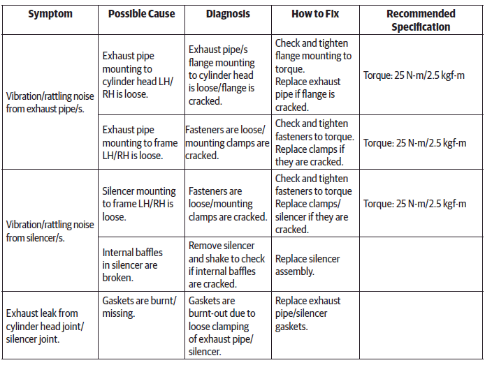
NOTE
- The troubleshooting given in this section is only related to issues with noise/leak in the exhaust system. For complaints related to poor pickup, misfiring, etc., please refer to engine section.
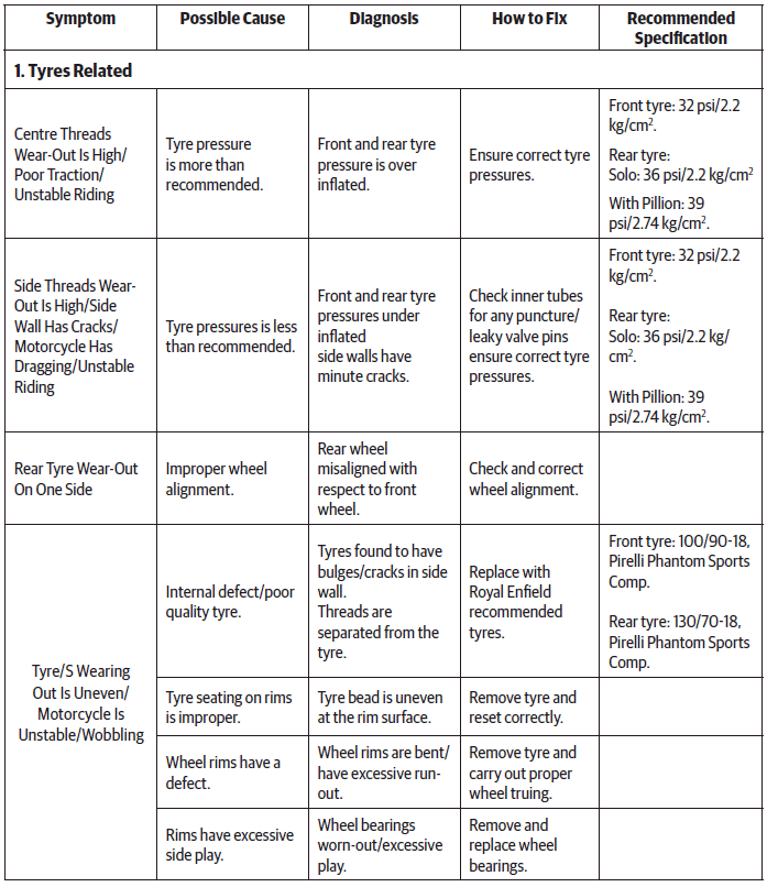
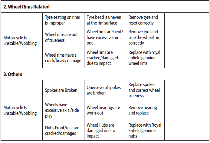
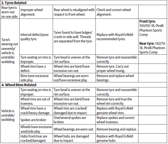
Wheels
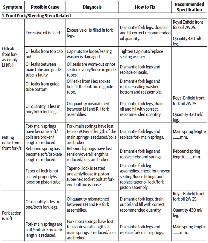
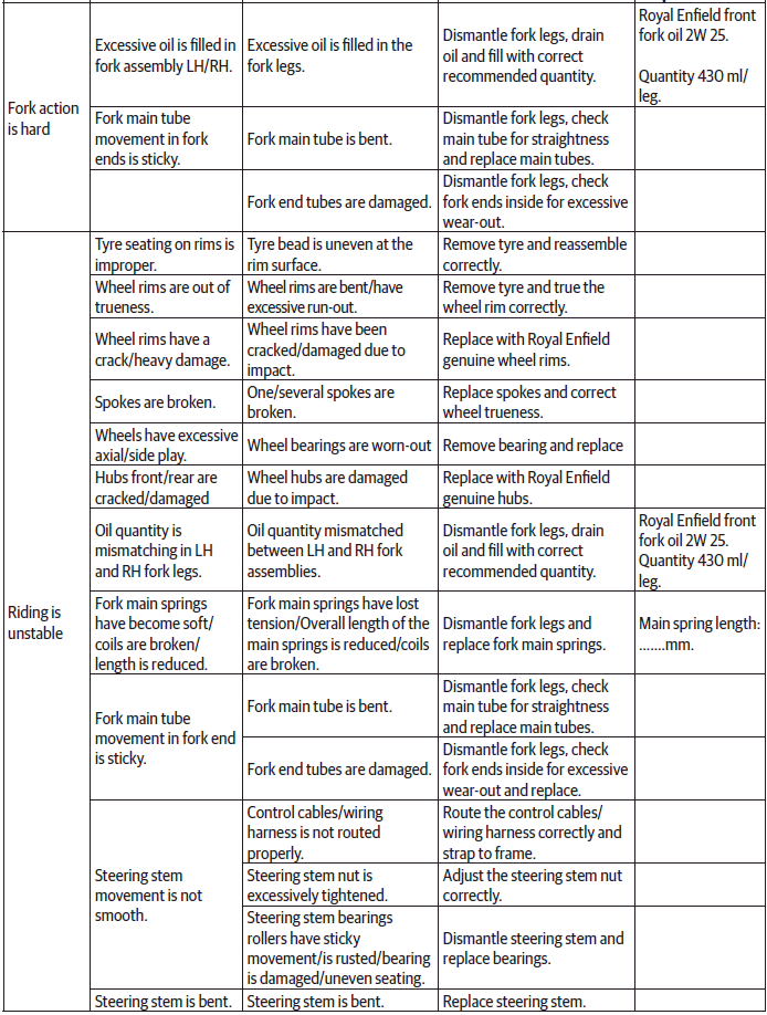
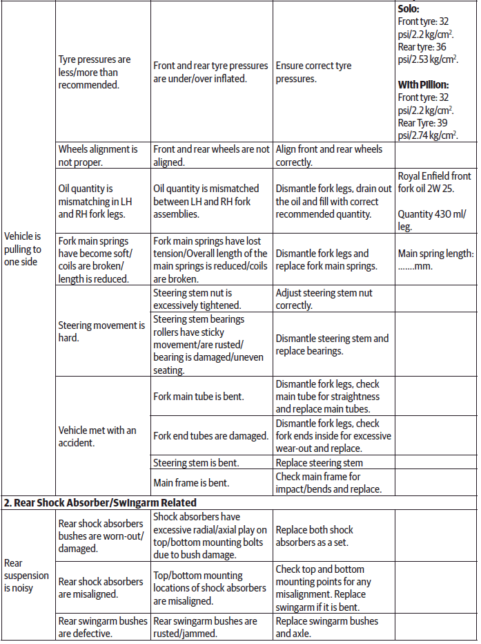
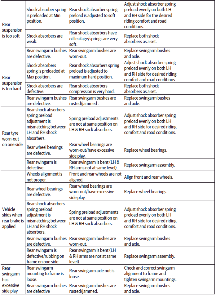
Suspension
See also:
 Royal Enfield Interceptor 650 - Service manual > Brake Lamp Connectors Assembly
Brake Lamp Connector - Rear Connect rear brake lamp connector (a) and ensure it is locked properly.
 Rider's Manual BMW R 1250 GS GSA
 Owner's Manual Harley-Davidson Sportster XL1200X Forty-Eight
 Owner's Manual Honda CBR650R
 Service manual Honda CBR650
 Owner's Manual Honda PCX125
 Owner's Manual Kawasaki Z1000SX
 Service manual Kawasaki Z1000SX
 Owner's Manual Lexmoto Echo
 Owner's Manual Royal Enfield Interceptor 650
 Service manual Royal Enfield Interceptor 650
 Owner's Manual Yamaha MT-07