 Royal Enfield Interceptor 650 - Service manual > Front Wheel Assembly
Front Wheel and Brake Disc
Dismantling
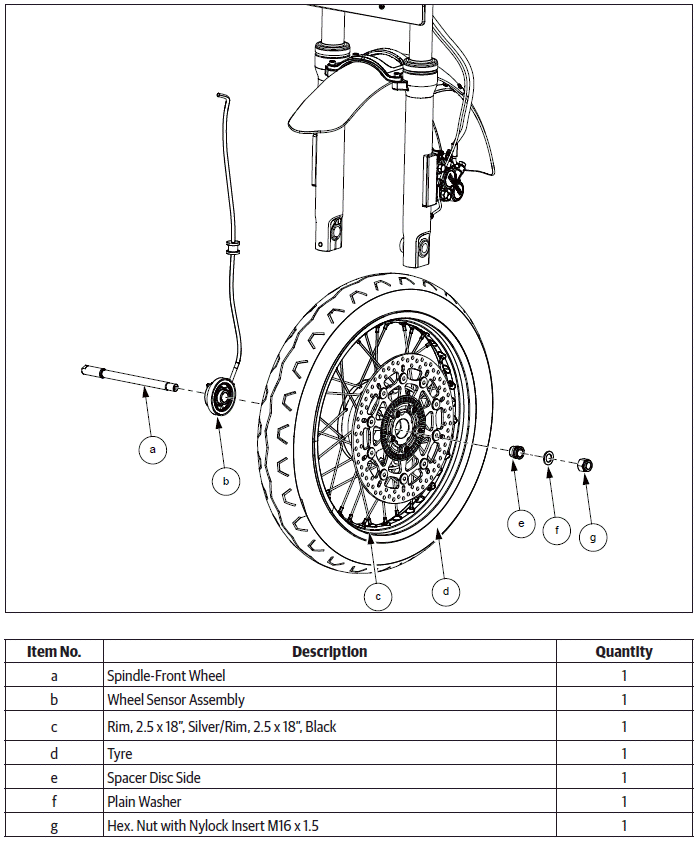
Front Wheel Assembly
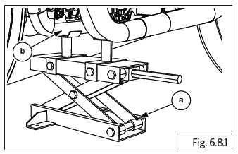
CAUTION Ensure the motorcycle is upright on a firm and flat surface.
- Locate a scissor jack (a) under the cradle frame (b) and lift motorcycle such that the front wheel is off the ground by minimum 6 inches (or 15 cm).
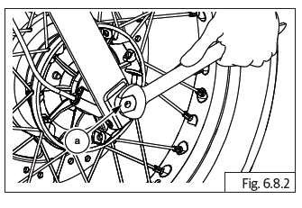
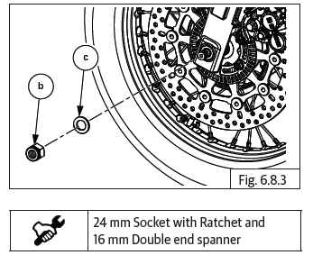
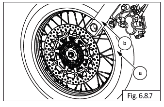
- Hold spindle (a) from RH with spanner and loosen and remove Hex nut (M16) (b) along with washer (c) from LH.
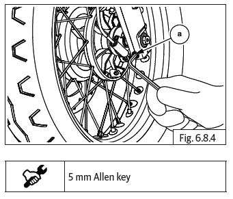
- Loosen Hex socket head bolt (M6) (a) from front fork assembly RH.
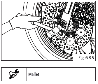
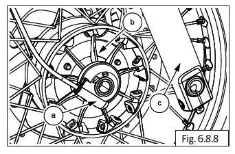
- Gently tap spindle (a) using mallet (b) from LH.
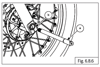
- Gently remove spindle (a) from wheel hub and front fork assembly RH (b).
CAUTION Ensure the wheel speed sensor cable does not get stretched and damaged. Support wheel from bottom while removing spindle.
- Gently lower the wheel (a) such that it comes out of the fork legs (b).
- Gently remove wheel speed sensor assembly (a) located between wheel hub (b) and fork assembly RH (c) and support suitably.
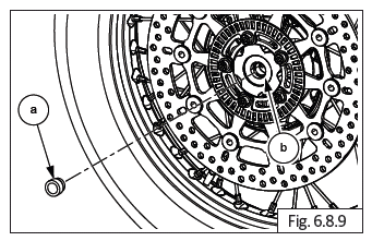
- Remove spacer (a) from wheel hub (b) on LH.
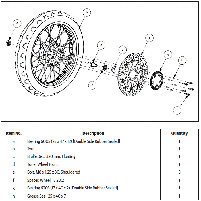
Front Wheel and Brake Disc
WARNING DO NOT place/store the wheel with disc facing downward. It will damage and change disc warpage.
CAUTION Place a soft cloth under the wheel hub center mounting hole area to prevent damage.
Please loosen thread sealant applied screws with care.
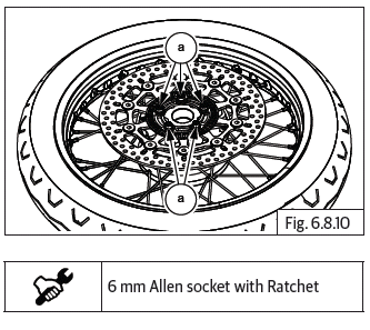
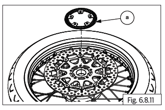
- Loosen and remove 5 Nos. Hex socket head bolts (M8) (a) holding disc plate to hub, in crisscross pattern.
- Remove toner wheel front (a) from hub and store carefully.
CAUTION Avoid any bends or damages to the toner wheel as it will affect the functioning of ABS.
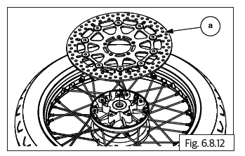
- Remove front brake disc (a) from hub and store carefully.
CAUTION Ensure the brake disc does not get damaged as it will affect the brake efficiency.
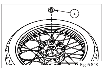
- Remove grease seal (a) from LH.
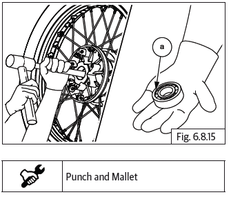
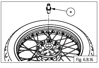
- Locate a suitable pointed punch on hole in spacer from RH of hub to remove bearing LH (a).
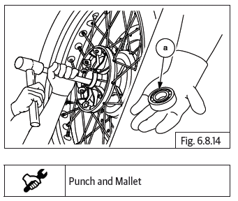
- Insert a punch into hub from LH side and drive out bearing RH (a).
- Remove spacer LH (a).
Rear Wheel Assembly
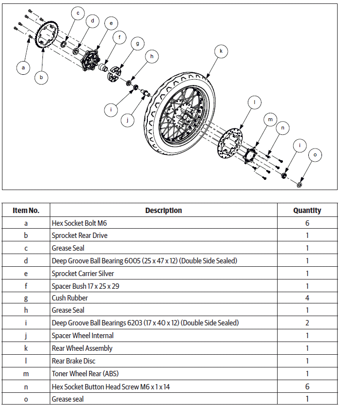
Rear Wheel and Brake Disc
See also:
 Royal Enfield Interceptor 650 - Service manual > Rear Wheel from Swing Arm
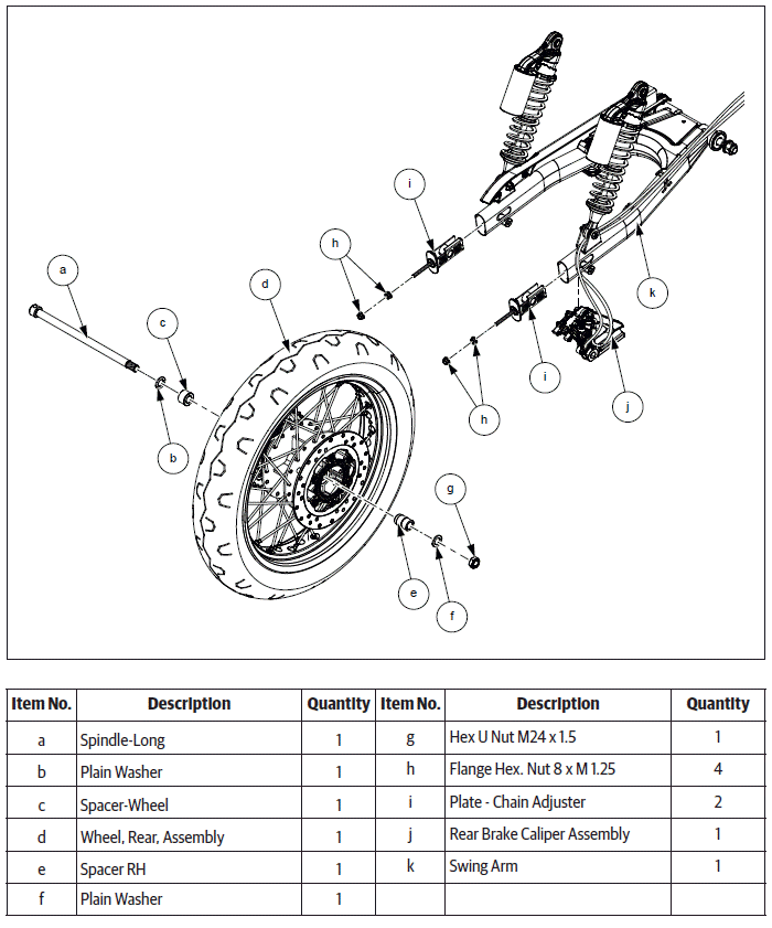
CAUTION Ensure the motorcycle is upright on a firm and flat surface. Locate a scissor jack (a) under the cradle frame (b) and lift motorcycle such that the rear wheel is off the ground. Loosen and remove Hex axle nut (M16) (b) from RH and hold other side LH with tommy bar (a). Remove washer (a) from spindle (b) on swing arm RH. Loosen lock nut (M8) (a) and adjuster nut (b) on both LH and RH chain adjusters. Gently tap spindle (a) from RH to pull out from LH. Push rear wheel forward to increase chain slack on rear sprocket. Remove chain adjuster assembly (a) from swing arm RH (b). Remove spindle (a) from rear wheel LH along with washer (b). Gently remove chain adjuster assembly (a) from swing arm LH (b). Slide out and remove brake caliper (a) with bracket.
 Rider's Manual BMW R 1250 GS GSA
 Owner's Manual Harley-Davidson Sportster XL1200X Forty-Eight
 Owner's Manual Honda CBR650R
 Service manual Honda CBR650
 Owner's Manual Honda PCX125
 Owner's Manual Kawasaki Z1000SX
 Service manual Kawasaki Z1000SX
 Owner's Manual Lexmoto Echo
 Owner's Manual Royal Enfield Interceptor 650
 Service manual Royal Enfield Interceptor 650
 Owner's Manual Yamaha MT-07