 Royal Enfield Interceptor 650 - Service manual > Rear Wheel from Swing Arm
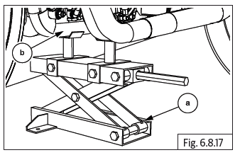
CAUTION Ensure the motorcycle is upright on a firm and flat surface.
- Locate a scissor jack (a) under the cradle frame (b) and lift motorcycle such that the rear wheel is off the ground.
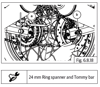
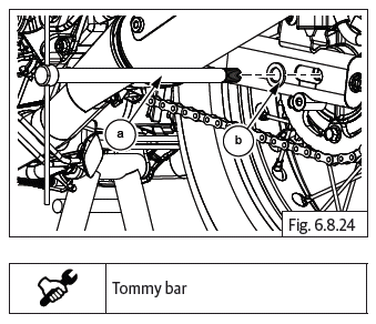
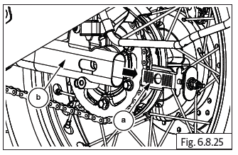
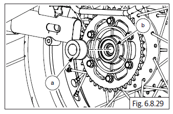
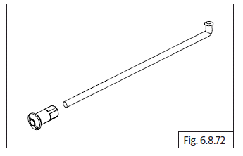
- Loosen and remove Hex axle nut (M16) (b) from RH and hold other side LH with tommy bar (a).
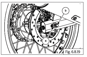
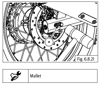
- Remove washer (a) from spindle (b) on swing arm RH.
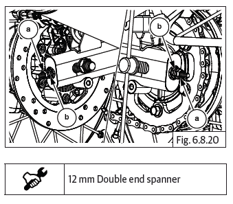
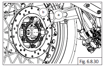
- Loosen lock nut (M8) (a) and adjuster nut (b) on both LH and RH chain adjusters.
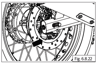
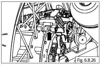
- Gently tap spindle (a) from RH to pull out from LH.
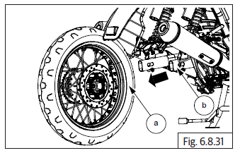
- Push rear wheel forward to increase chain slack on rear sprocket.
- Remove chain adjuster assembly (a) from swing arm RH (b).
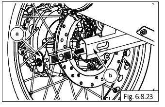
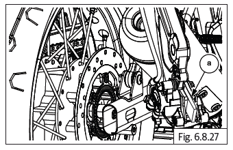
- Remove spindle (a) from rear wheel LH along with washer (b).
- Gently remove chain adjuster assembly (a) from swing arm LH (b).
- Slide out and remove brake caliper (a) with bracket.
CAUTION Support the caliper carefully and ensure it does not get damaged.
- Ensure limiter pad (a) is placed between brake pads in caliper assembly.
- Gently release drive chain (a) from sprocket (b).
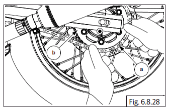
- Gently remove spacer LH (a) from the rear wheel hub (b).
- Gently remove spacer RH (a) from the rear wheel hub (b).
- Gently remove rear wheel (a) from swing arm (b).
Rear Wheel and Brake Disc
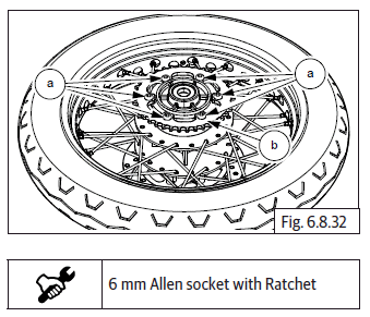
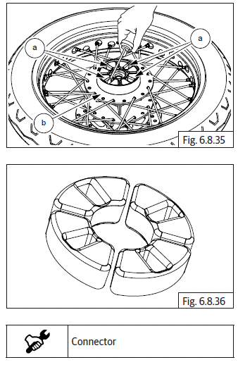
- Loosen and remove 6 Nos. Hex flanged socket head bolts (M8) (a) to remove chain sprocket (b).
- Remove chain drive sprocket (a) from sprocket carrier (b).
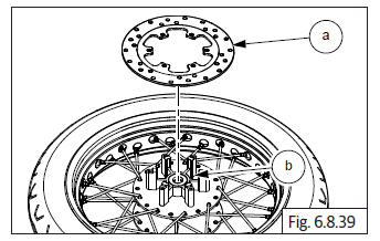
- Remove sprocket carrier (a) from the rear wheel hub (b).
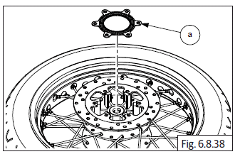
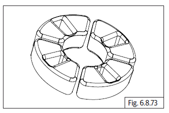
- Remove 4 Nos. cush rubbers (a) from rear wheel hub LH (b).
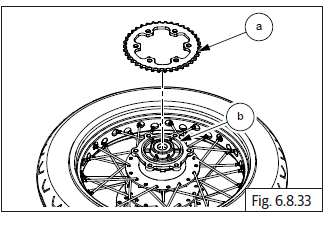
- Loosen and remove 6 Nos. Hex head button socket screws (M6) (a) to remove ABS toner.
- Remove ABS toner wheel (a) from rear wheel RH.
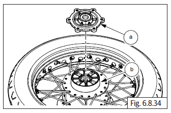
- Remove rear brake disc (a) from the rear wheel hub RH (b).
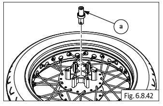
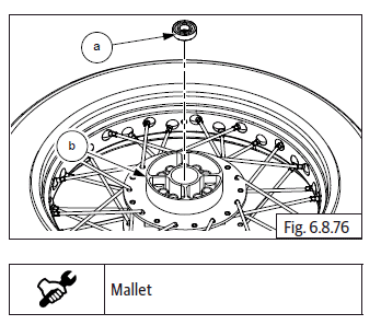
- Remove grease seal (a).
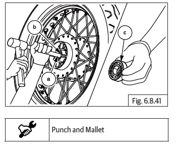
- Insert a punch (a) into hub (b) from LH side and drive out bearing RH (c).
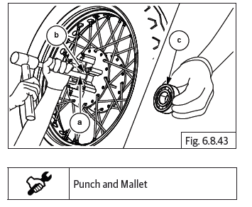
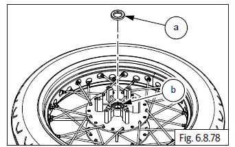
- Remove spacer (a) from the rear wheel hub RH.
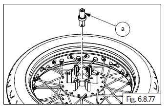
- Locate a suitable pointed punch (a) on hole in spacer from RH of hub (b) to remove bearing LH (c).
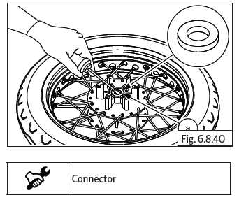
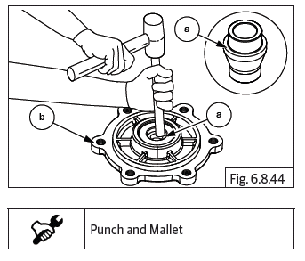
- Gently tap to remove spacer (a) from sprocket carrier (b).
CAUTION DO NOT apply excessive force to remove the bearing, spacer as it may cause damage.
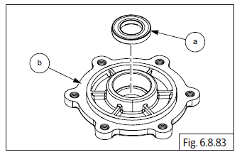
- Gently remove grease seal (a) from the sprocket carrier (b).
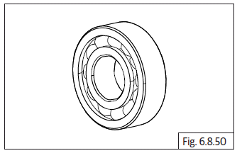
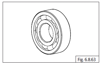
- Gently remove bearing (6005) (a) from the sprocket carrier (b).
Inspection
Front Wheel and Brake Disc
- Inspect tyre condition and wheel rim for any damages or bends and replace if out of specifications.
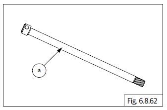
- Inspect and replace spindle (a) if it has excess wear, rust or bends.
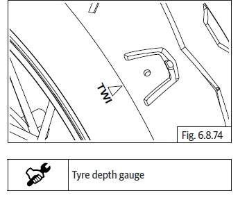
- Check tyres for any uneven wear out and the sipes on the center of the tyre is above the TWI index.
- Check noise and play on bearing LH and RH.
- Check and replace wheel spacer if it has excess wear-out.
- Check if wheel hub assembly is cracked or damaged and replace.
- Check and replace wheel hub bearing seated portion if there is any scoring.
- Inspect wheel rim run out and replace if out of specifications.
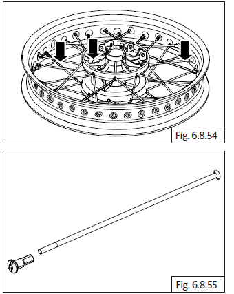
- Inspect condition of wheel spokes and wheel rim for any damages or bends and loose ends. Replace if necessary.
- Inspect for rust, deep scoring, any foreign materials, burn marks crack in the mounting location of brake disc.
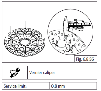
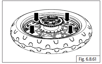
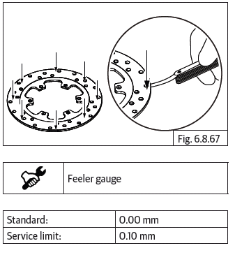
- Inspect brake disc thickness and run-out. Measure depth at points where scoring is found on the discs and replace if there is excess wear.
- Also measure thickness at the points indicated in the illustration and replace disc if out of specifications.
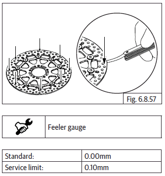
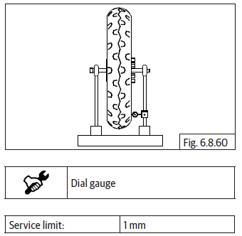
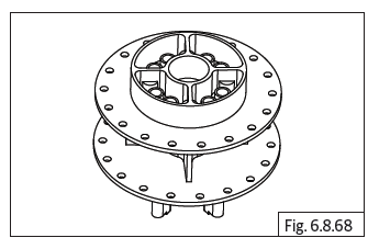
- Place brake disc rotor on a flat surface and inspect warpage. Replace if it is out of specifications.
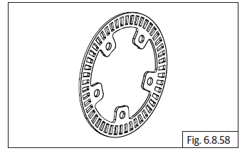
- Inspect and replace toner wheel plate if there are any damages or bends.
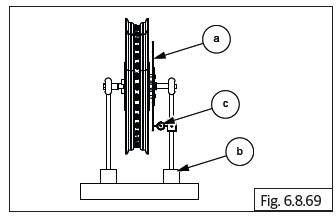
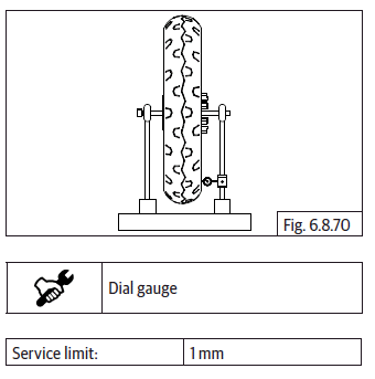
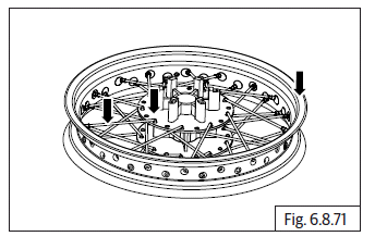
- After assembly of brake disc (a) into front wheel, insert spindle into rim, fix on wheel balance frame (c) and rotate rim to check the disc run-out with dial gauge (b). Ensure run-out is within specified limits.
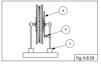
- Similarly check run-out of front and rear wheels.
NOTE
- Run-out of brake disc should be checked only when brake disc is assembled on wheel hub.
Rear Wheel and Brake Disc
- Inspect tyre condition and wheel rim for any damages or bends and replace if doesn't meet the specifications.
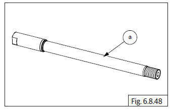
- Inspect and replace spindle (a) if it has excess wear, rust or bends.
- Check noise and play on bearing LH and RH. Replace if necessary.
- Check and replace spacer if it has excess wear-out.
- Inspect ABS toner wheel (a) for any bends or damages.
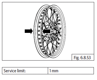
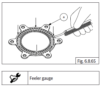
- Place ABS toner wheel on a flat surface and check warpage. Replace if out of specifications.
- Inspect for rust, deep scoring, any foreign materials, burn marks crack in the mounting location of brake disc.
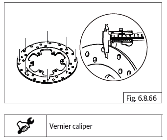
- Inspect brake disc thickness and run-out. Measure depth at points where scoring is found on the discs and replace if there is excess wear.
- Also measure thickness at the points indicated in the illustration and replace disc (a) if out of specifications.
- Place brake disc rear on a flat surface and check warpage. Replace if out of specifications.
- Inspect wheel hub assembly for any cracks or damages. Replace if out of specifications.
- Inspect if hub bearing seating portion has scoring. Replace if out of specifications.
- After assembly of brake disc (a) into front wheel, insert spindle into rim, fix on wheel balance frame (c) and rotate rim to check the disc run-out with dial gauge (b). Ensure run-out is within specified limits.
CAUTION Run-out of brake disc should be checked only when brake disc is assembled on wheel hub.
- Similarly check run out of front and rear wheel.
- Inspect condition of wheel spokes and wheel rim for any damages or bends and loose ends. Replace if necessary.
- Inspect and replace spokes if it has excess wear, rust or bends.
- Check rear wheel hub cushion rubbers for any wear-out or damages.
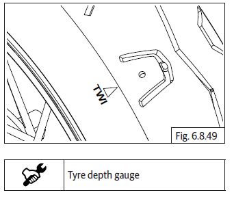
- Check tyres for any uneven wear out and the sipes on the center of the tyre is above the TWI index.
Assembly
Tyre Assembly On Wheel Rim
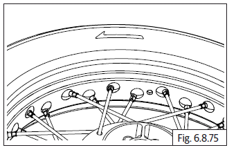
- Ensure the tyre is assembled on the wheel rim with the arrow on the tyre side wall is facing towards the front.
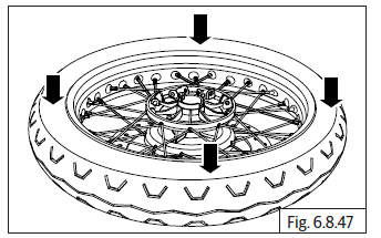
- Inflate tyre to the recommended pressure and ensure the tyre is evenly seated in the rim on both LH and RH sides.
Rear Wheel and Brake Disc
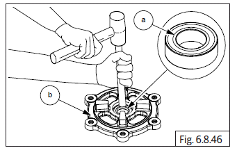
- Locate bearing LH (a) into rear wheel hub RH (b). Gently tap on the bearing and ensure it is seated properly on the hub.
- Assemble spacer (a) into rear wheel hub RH. Ensure it is properly seated on the bearing surface.
- Locate bearing RH (a) into rear wheel hub LH (b). Gently tap on the bearing and ensure it is seated properly on the hub.
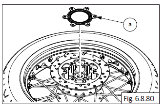
- Assemble rear brake disc (a) into rear wheel hub RH (b).
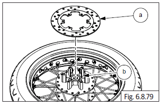
- Assemble ABS toner wheel (a) into rear brake disc on rear wheel RH.
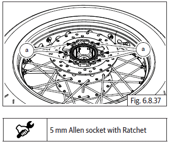
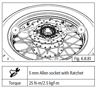
- Use recommended sealant on the screws and locate and tighten 6 Nos. Hex head button socket screws (M6) (a) into rear wheel disc hub RH.
- Clean cushion rubbers seating area and insert 4 Nos. cushion rubbers (a) into rear wheel hub LH and gently tap with mallet.
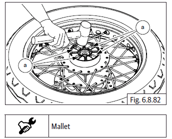
NOTE
- Always use new cushion rubbers as they are for one time usage only.
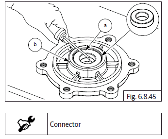
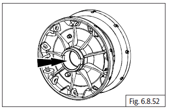
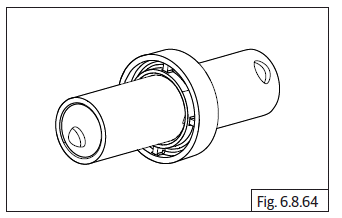
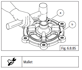
- Locate bearing (a) into sprocket carrier (b). Ensure it is properly seated on the slot.
- Assemble grease seal (a) into sprocket carrier (b).
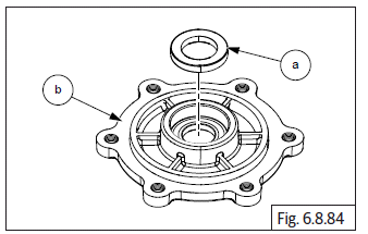
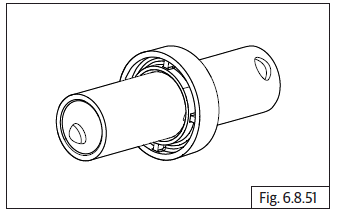
- Locate and gently tap the spacer (a) into sprocket carrier (b).
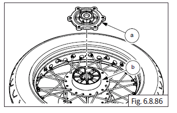
- Assemble rear sprocket carrier (a) over cushion rubbers into rear wheel hub LH (b).
- Locate chain drive sprocket (a) into sprocket carrier (b) on rear wheel hub LH.
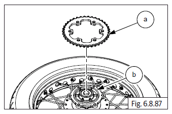
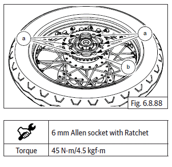
- Locate and tighten 6 Nos. Hex flanged socket head bolts (M8) (a) into carrier (b) on rear wheel LH.
See also:
 Royal Enfield Interceptor 650 - Service manual > Front Wheel Assembly
Front Wheel and Brake Disc
Royal Enfield Interceptor 650 - Service manual > Rear Wheel into Swing Arm
Gently locate rear wheel (a) into swing arm (b). Insert spacer (a) into rear wheel hub RH (b). Locate drive chain (a) onto sprocket (b) and align wheel into swing arm. Remove limiter pad and slide brake caliper (a) on to brake disc. Assemble chain adjuster assembly (a) into swing arm LH (b). Assemble chain adjuster assembly (a) into swing arm RH (b). Insert spindle (a) with tommy bar into rear wheel hub LH along with washer (b). Install washer (a) into spindle RH (b). Assemble Hex nut (M16) (a) and tighten into swing arm. After completing rear wheel assembly into motorcycle, ensure chain slack is as per specifications.
 Rider's Manual BMW R 1250 GS GSA
 Owner's Manual Harley-Davidson Sportster XL1200X Forty-Eight
 Owner's Manual Honda CBR650R
 Service manual Honda CBR650
 Owner's Manual Honda PCX125
 Owner's Manual Kawasaki Z1000SX
 Service manual Kawasaki Z1000SX
 Owner's Manual Lexmoto Echo
 Owner's Manual Royal Enfield Interceptor 650
 Service manual Royal Enfield Interceptor 650
 Owner's Manual Yamaha MT-07