 Royal Enfield Interceptor 650 - Service manual > Rear Wheel into Swing Arm
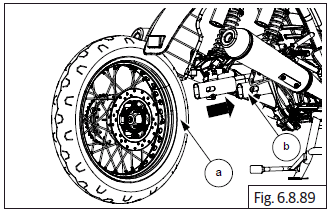
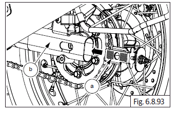
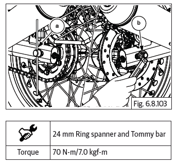
- Gently locate rear wheel (a) into swing arm (b).
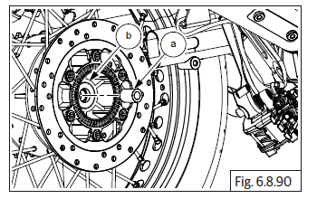
- Insert spacer (a) into rear wheel hub RH (b).
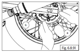
- Locate drive chain (a) onto sprocket (b) and align wheel into swing arm.
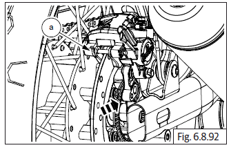
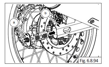
- Remove limiter pad and slide brake caliper (a) on to brake disc.
- Assemble chain adjuster assembly (a) into swing arm LH (b).
- Assemble chain adjuster assembly (a) into swing arm RH (b).
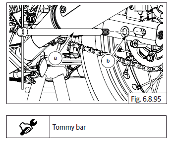
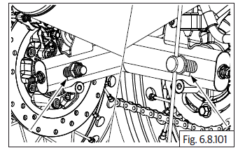
- Insert spindle (a) with tommy bar into rear wheel hub LH along with washer (b).
- Install washer (a) into spindle RH (b).
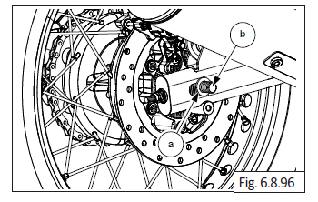
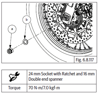
- Assemble Hex nut (M16) (a) and tighten into swing arm.
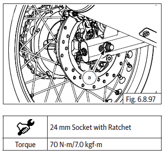
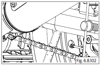
- After completing rear wheel assembly into motorcycle, ensure chain slack is as per specifications.
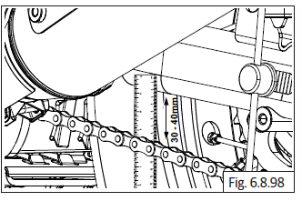
Drive Chain Free Play Adjustment
- Inspect chain free play at 3 locations using a ruler. Free play for drive chain should be between 30 mm to 40 mm.
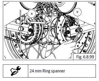
- If the free play of the drive chain is not between 30 mm to 40 mm then hold spindle (a) on LH using a tommy bar and loosen (M16) (b) axle nut on RH.
- To reduce free play loosen the lock nut (M8) (a) in counter clockwise and tighten the adjuster nut (M8) (b) in clockwise both LH and RH.
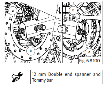
- Ensure the lines are matched with the lines punched in swing arm on both LH & RH side for proper wheel alignment.
- Now measure the drive chain free play using ruler and it should be between 30 mm to 40 mm.
CAUTION Chain slackness beyond 40 mm will lead to chain slippage or breakage.
- Once chain free play is verified, hold spindle LH with tommy bar (a) and tighten the wheel axle nut (M16) (b).
Tyre Assembly on Wheel Rim
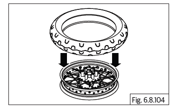
- Ensure the tyre is assembled on the wheel rim with the arrow on the tyre side wall is facing towards the front.
- Inflate tyre to the recommended pressure and ensure the tyre is evenly seated in the rim on both LH and RH sides.
Front Wheel and Front Brake Disc
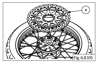
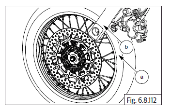
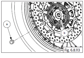
- Locate front brake disc (a) on wheel hub with the disc facing up. Ensure six mounting holes are correctly aligned.
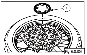
- Position toner wheel (a) on front disc and ensure mounting holes are correctly aligned.
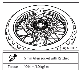
- Apply thread sealant on the 6 Nos Hex socket head bolts (M6) (a) and allow it to dry for a few minutes.
- Locate the bolts on the mounting holes and tighten toner ring and brake disc to the wheel hub in crisscross patten to specified torque.
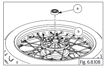
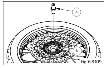
- Insert bearing (6203) (a) into front wheel hub RH (b).
- Insert bearing spacer (a) from LH side of front hub (b).
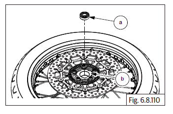
- Insert bearing (a) into wheel hub LH (b).
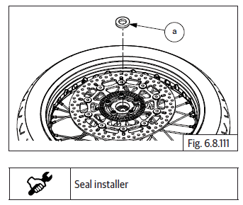
- Install grease seal (a) into wheel hub LH with seal installer.
Front Wheel into Front Fork Assembly
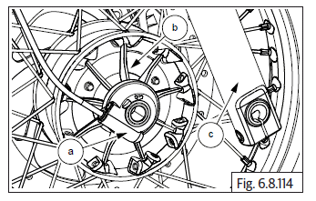
- Carefully align front wheel (a) into front fork assembly (b).
- Insert spacer (a) in to wheel hub (b) from LH.
- Gently align wheel speed sensor assembly (a) between wheel hub (b) and the front fork assembly RH (c).
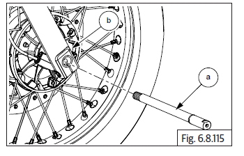
- Insert spindle (a) into front fork assembly RH and wheel hub (b).
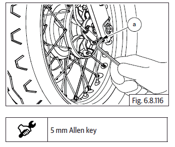
- Tighten Hex socket bolt (M6) (a) into front fork assembly RH.
- Insert Hex nut (M16) (a) along with washer (b) into spindle bolt on LH.
- Hold spindle with spanner from RH and gently tighten Hex nut (M16) (a).
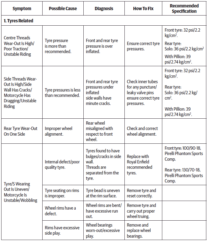
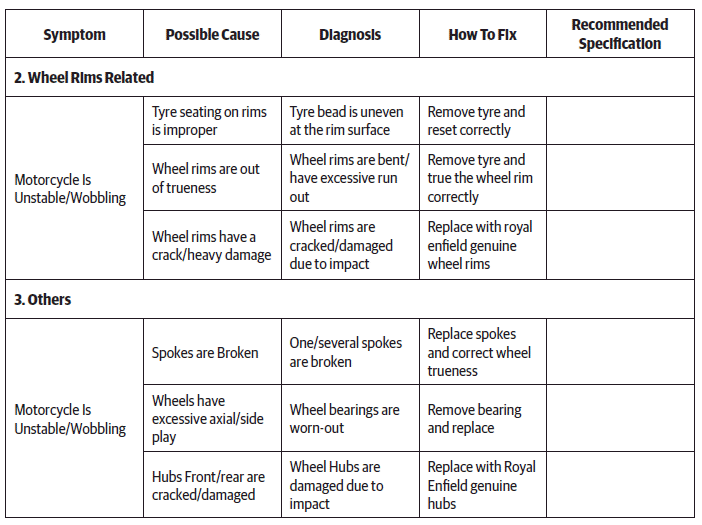
Troubleshooting
NOTE
- The trouble shooting given in this section is only related to the issues with wheels. For complaints related to other issues such as poor suspension action/handling/unstable ride please refer to suspension.
See also:
 Royal Enfield Interceptor 650 - Service manual > Rear Wheel from Swing Arm
CAUTION Ensure the motorcycle is upright on a firm and flat surface. Locate a scissor jack (a) under the cradle frame (b) and lift motorcycle such that the rear wheel is off the ground. Loosen and remove Hex axle nut (M16) (b) from RH and hold other side LH with tommy bar (a). Remove washer (a) from spindle (b) on swing arm RH. Loosen lock nut (M8) (a) and adjuster nut (b) on both LH and RH chain adjusters. Gently tap spindle (a) from RH to pull out from LH. Push rear wheel forward to increase chain slack on rear sprocket. Remove chain adjuster assembly (a) from swing arm RH (b). Remove spindle (a) from rear wheel LH along with washer (b). Gently remove chain adjuster assembly (a) from swing arm LH (b). Slide out and remove brake caliper (a) with bracket.
Royal Enfield Interceptor 650 - Service manual > Suspension
Front Fork Assembly Removal from Motorcycle Front Fork LH and RH
 Rider's Manual BMW R 1250 GS GSA
 Owner's Manual Harley-Davidson Sportster XL1200X Forty-Eight
 Owner's Manual Honda CBR650R
 Service manual Honda CBR650
 Owner's Manual Honda PCX125
 Owner's Manual Kawasaki Z1000SX
 Service manual Kawasaki Z1000SX
 Owner's Manual Lexmoto Echo
 Owner's Manual Royal Enfield Interceptor 650
 Service manual Royal Enfield Interceptor 650
 Owner's Manual Yamaha MT-07