 Royal Enfield Interceptor 650 - Service manual > Fuel Pump Connector and Fuel Level Sensor
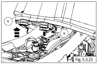
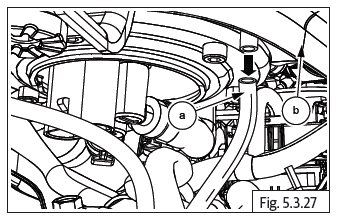
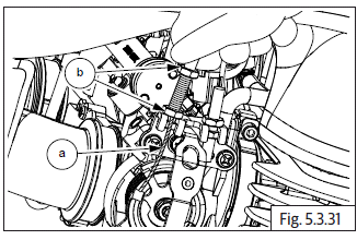
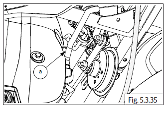
- Gently lift the fuel tank upwards to access the fuel pump connector.
- Disconnect the fuel pump connector (a) from fuel tank (b).
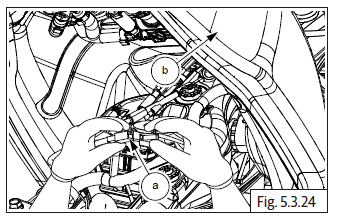
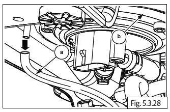
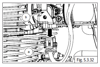
- Disconnect fuel level sensor connector (a) from fuel tank (b).
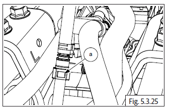
Fuel Hose (Fuel Pump to Injector)
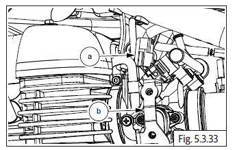
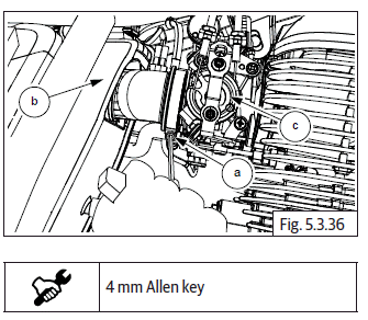
- Locate the fuel feed hose connector (fuel pump to injector rail) (a) under the fuel tank.
- Disconnect quick joint connector (a) from pipe (b) by pressing the lock button (c).
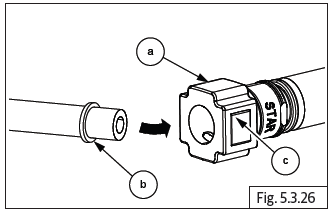
WARNING Fuel pressure may still in line; crank engine to release pressure in the fuel line.
EVAP Connections on Fuel Tank
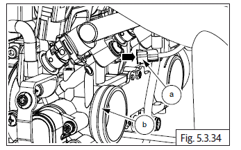
- Disconnect EVAP connection hose (a) from fuel tank (b).
Drain Hose
- Disconnect drain hose connection (a) from fuel tank (b).
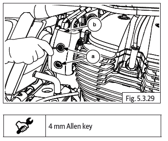
Throttle Body Covers on LH and RH
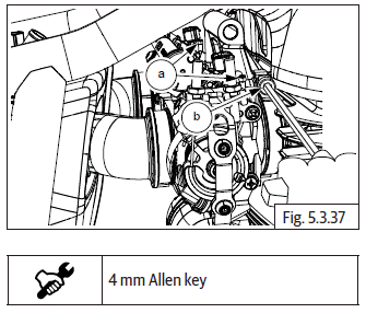
- Loosen and remove 2 Nos. Hex socket bolts (M5) (a) from RH and LH throttle body cover (b).
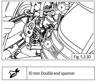
Throttle Cable
(Connection on Throttle Body)
- Loosen 2 Nos. Hex head nuts (M6) (a) on RH throttle body (b) to release the tension in throttle cable.
- Gently pull throttle cable (a) out from bracket to release the adjuster and lock nuts (b) from throttle body.
- Repeat the procedure to release the other throttle cable.
Injector, TPS, MAPS, ISC Connections
Throttle Position Sensor (TPS), Manifold Absolute Pressure (MAP) Sensor and Idle Speed Controller (ISC)
- Disconnect throttle position sensor connector (a) from LH throttle body (b).
- Gently press connector lock to disconnect fuel injector connectors (a) from LH and RH of throttle body (b).
- Disconnect idle speed control sensor connector (a) from throttle body (b).
Reed Valve Connection
- Disconnect Reed valve hose (a) from front side of engine cylinder head.
Air Filter Housing to Throttle Body
- Locate LH and RH worm clips on throttle body to air filter box.
- Loosen both LH and RH worm clip screws (M5) (a) and separate the air filter housing (b) from throttle body (c).
Throttle Body
- Ensure throttle position sensor, manifold absolute pressure sensor and idle speed controller wiring connectors are disconnected.
- Disconnect the hoses (a) from canister purge valve.
- Loosen LH and RH worm clip screws (M5) (b) to disconnect throttle body from inlet manifolds.
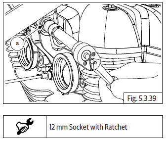
Engine Steady Bracket
- Support the bottom of engine suitably.
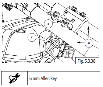
- Locate steady bracket (a) on center of main frame (b).
- Loosen and remove Hex socket head bolt (M8) (c) on LH side and hold hex nut on RH.
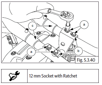
- Remove Hex nut (M8) (a) and washer from RH side.
Engine Cylinder Head Steady Bracket
- Remove 4 Nos. Hex flange head bolts (M8) (a) from LH and RH steady brackets (b) located on center of main frame (c).
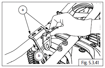
- Remove the LH and RH steady brackets (a) from frame (b).
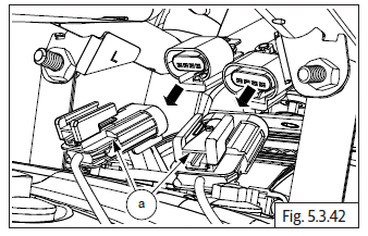
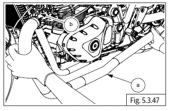
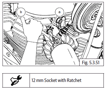
Hego/Oxygen Sensor Connectors
- Disconnect Hego/oxygen sensor connectors (a) from both LH and RH located on front side of engine.
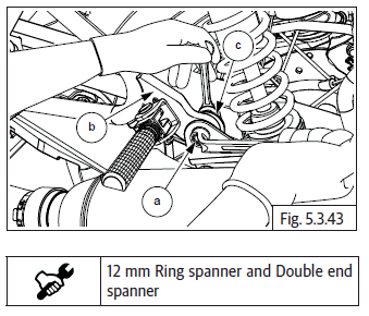
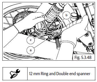
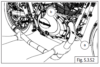
Exhaust Pipe and Silencer LH
- Locate LH silencer bracket attached on rear end of the frame/near to shock absorber.
- Loosen and remove Hex head flange bolt (M8) (a) from frame bracket (b). Locate and support the outer end Hex nut (M8) (c) suitably.
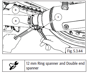
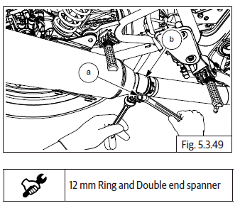
- Loosen and remove Hex flange head bolt (M8) (a) on clamp (b) (exhaust pipe to silencer). Locate and support the outer end Hex nut (M8) (c) suitably.
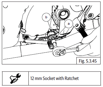
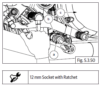
- Loosen and remove Hex head flange bolt (M8) (a) on frame (b) located below the front bottom of LH cover.
- Loosen and remove 2 Nos. Hex nuts (M8) (a) on engine LH side to disconnect LH exhaust pipe (b) from cylinder head (c).
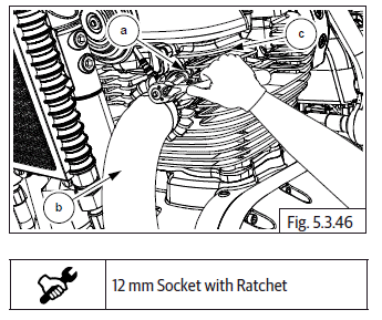
- Gently remove the LH exhaust pipe (a) along with Hego/oxygen sensor (b) from cylinder head.
Exhaust Pipe and Silencer RH
- Loosen and remove Hex flange head bolt (M8) (a) from frame bracket (b). Locate and support the outer end Hex nut (M8) (c) suitably.
- Loosen and remove Hex head flange bolt (M8) (a) from clamp (b) (exhaust pipe to silencer). Locate and support the outer end Hex nut (M8) suitably.
- Loosen and remove Hex head flange bolt (M8) (a) from main frame (b) located on bottom of clutch cover/below to rear brake lever (c).
- Loosen and remove 2 Nos. Hex nuts (M8) (a) from cylinder head (b).
- Gently remove the RH exhaust pipe (a) along with Hego/oxygen sensor (b).
See also:
 Royal Enfield Interceptor 650 - Service manual > Engine Oil
NOTE Ensure the motorcycle is placed on a firm flat surface, resting it on the center stand/ramp. Before starting the dismantling process, start the engine and let the engine warm up for a few minutes and then turn it OFF. Remove engine oil filler cap (a). Place a tray (a) under engine oil magnetic drain plug (M14) (b). Remove it along with washer (c) to drain oil completely from engine.
Royal Enfield Interceptor 650 - Service manual > Magneto/Gear Position/Side Stand
Magneto/Gear Position/Side Stand Switch Couplers Connections Disconnect the gear position sensor (a) located on rear side of engine (b). Disconnect magneto sensor connector (a) located on rear side of engine (b). Disconnect side stand switch connector (a) located on rear bottom of engine (b). Disconnect crank position sensor connector (c).
 Rider's Manual BMW R 1250 GS GSA
 Owner's Manual Harley-Davidson Sportster XL1200X Forty-Eight
 Owner's Manual Honda CBR650R
 Service manual Honda CBR650
 Owner's Manual Honda PCX125
 Owner's Manual Kawasaki Z1000SX
 Service manual Kawasaki Z1000SX
 Owner's Manual Lexmoto Echo
 Owner's Manual Royal Enfield Interceptor 650
 Service manual Royal Enfield Interceptor 650
 Owner's Manual Yamaha MT-07