 Royal Enfield Interceptor 650 - Service manual > Fuel Tank
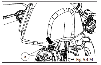
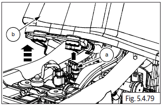
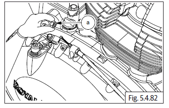
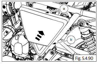
- Locate and slide the fuel tank into front frame guides (a).
EVAP to Fuel Tank Connections
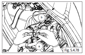
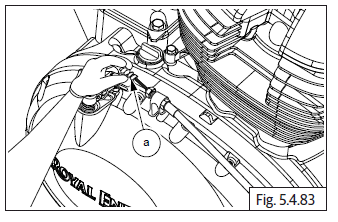
- Connect drain connection hose (a) to fuel tank (b).
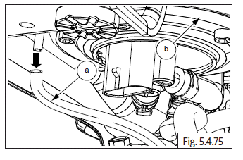
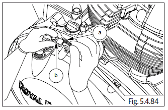
- Connect the EVAP connection hose (a) to the fuel tank (b).
Fuel Hose (Fuel Pump to Injector)
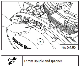
- Connect fuel feed hose quick connector (a) (fuel pump to injector rail).
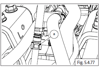
NOTE
- Ensure fuel quick coupler is locked properly. (There should be a "Click" sound when locked)
Fuel Level Sensor and Fuel Pump
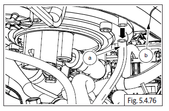
- Connect fuel level sensor connectors (a) in fuel tank (b).
- Connect the fuel pump connector (a) into the fuel tank (b).
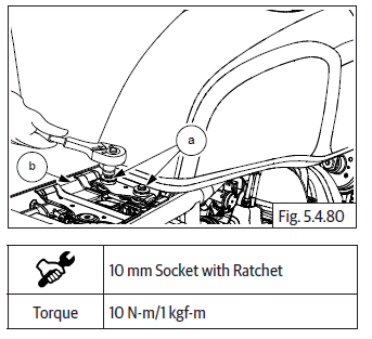
- Tighten with 2 Nos. Hex head bolts (M6) (a) into fuel tank (b) on frame.
Clutch Cable
NOTE
- Ensure clutch cable is properly routed and retained by all necessary clips.
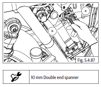
- Locate lower end of clutch cable (a) into guide (b).
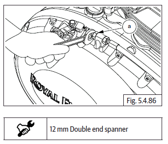
- Install outer lock Hex nut (M8) (a).
- Install rubber grommet (a).
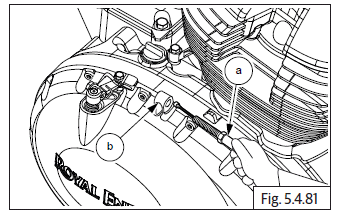
- Install inner cable (a) into clevis in the clutch release case (b).
- Install inner cable (a) into clevis in the clutch release case (b).
- Tighten outer lock nut (M8) (a).
Battery Connections
NOTE
- Ensure ignition and stop switches are in OFF position before connecting battery cables.
- For the precautions and procedures to remove and install cables refer General Information.
- Connect positive (+) terminal and tighten with Hex head bolt (M6) (a) on battery (b).
- Connect negative (-) terminal and tighten with Hex head bolt (M6) (a) on battery (b).
Seat Assembly
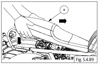
- Locate seat (a) into seat bracket properly and gently push to lock.
Side Panel LH and RH
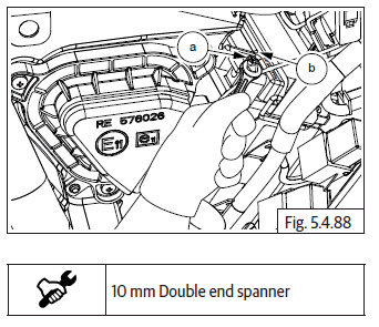
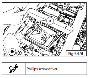
- Slide LH panel (a) from bottom to fit into frame (b).
- Insert and tighten Phillips head screw (a) located near ECU (b) to fix LH side panel.
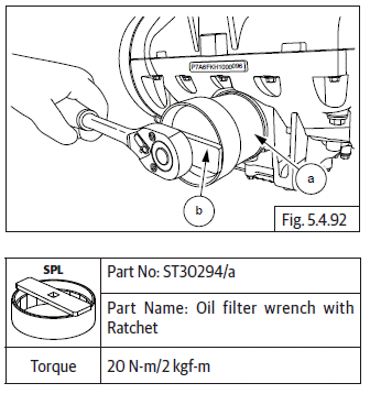
Oil Filter
- Locate and tighten oil filter (a) using special tool (b).
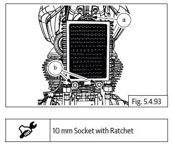
Oil Cooler Mountings to Frame
- Slide up cooler to top mounting bush and support cooler on frame (a).
- Tighten 2 Nos. Hex flange head bolts (M6) (b) along with washers and nuts from cooler mounting to frame.
See also:
 Royal Enfield Interceptor 650 - Service manual > Silencer RH on Exhaust Pipe
Ensure mounting clamp (a) on silencer (b) and is sufficiently loose. Assemble new gasket (c) on exhaust pipe and locate silencer on exhaust pipe. Duly ensure rear mounting bracket of silencer is aligned to the mounting hole of frame RH. Align silencer mounting bracket hole to main frame mounting hole. Insert Hex head bolt (M8) (a) into mounting bracket (b) along with washer and nut (c). Hold nut with suitable tool and tighten bolt to specified torque. Hold Hex head bolt (M8) (a) on clamp and ensure to position clamp on RH silencer (b) correctly and nut (c).
Royal Enfield Interceptor 650 - Service manual > Oil Cooler Inlet and Outlet Pipes
Oil Cooler Inlet and Outlet Pipes to Engine Insert bolt union crankcase (M16) (a) along with washers and tighten to specified torque. Tighten bolt (M18) (a) on oil cooler hose (b) by supporting (M16) (c) bolt on top. Tighten oil cooler inlet pipe with 2 Nos. Hex socket screws (M6) (a).
 Rider's Manual BMW R 1250 GS GSA
 Owner's Manual Harley-Davidson Sportster XL1200X Forty-Eight
 Owner's Manual Honda CBR650R
 Service manual Honda CBR650
 Owner's Manual Honda PCX125
 Owner's Manual Kawasaki Z1000SX
 Service manual Kawasaki Z1000SX
 Owner's Manual Lexmoto Echo
 Owner's Manual Royal Enfield Interceptor 650
 Service manual Royal Enfield Interceptor 650
 Owner's Manual Yamaha MT-07