 Royal Enfield Interceptor 650 - Service manual > Silencer RH on Exhaust Pipe
Engine / Engine Assembly to Frame / Silencer RH on Exhaust Pipe
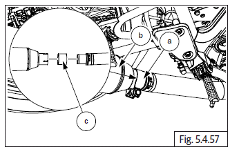
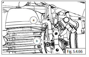
- Ensure mounting clamp (a) on silencer (b) and is sufficiently loose.
- Assemble new gasket (c) on exhaust pipe and locate silencer on exhaust pipe.
- Duly ensure rear mounting bracket of silencer is aligned to the mounting hole of frame RH.
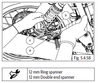
- Align silencer mounting bracket hole to main frame mounting hole.
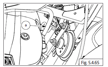
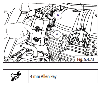
- Insert Hex head bolt (M8) (a) into mounting bracket (b) along with washer and nut (c). Hold nut with suitable tool and tighten bolt to specified torque.
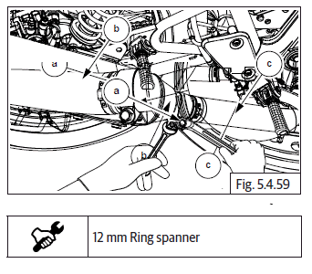
- Hold Hex head bolt (M8) (a) on clamp and ensure to position clamp on RH silencer (b) correctly and nut (c).
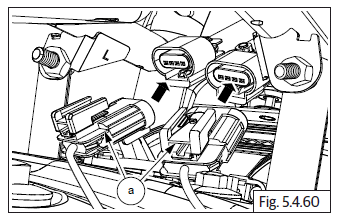
Hego/Oxygen Sensor Connectors
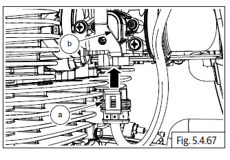
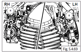
- Ensure Hego/oxygen sensors are tightened fully on exhaust pipes LH and RH.
- Connect LH and RH Hego/Oxygen sensor connectors (a).
- Ensure connectors are locked properly. (There is a "Click" sound when locked).
Throttle Body
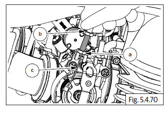
- Ensure clips (a) are in position on inlet manifolds and loosened sufficiently.
- Locate throttle body (b) on the inlet manifold rubber flanges (c) and ensure it is properly seated on both LH and RH inlet manifolds.
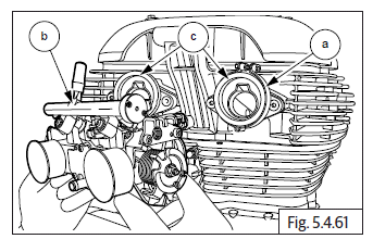
- Tighten both clips (a) sufficiently over inlet manifold.
- Ensure clips are in position on air filter hoses and loosened sufficiently.
- Locate air filter housing (b) on throttle body (c) and ensure it is properly seated on both LH and RH of throttle body.
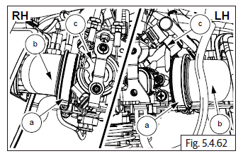
- Tighten both clips (a) sufficiently over air filter hose.
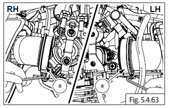
Air Filter Housing to Throttle Body
- Tighten worm clips screws (M4) (a) from air filter housing (b) to throttle body (c) on both LH and RH sides.
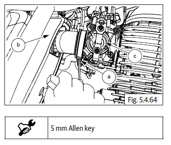
Reed Valve Connection
- Connect the reed valve hose (a).
Injector, TPS and Map Connections
- Connect the LH and RH injector connectors (a) located on throttle body (b).
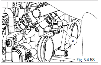
- Connect TPS sensor connector (a) to sensor (b) at bottom of throttle body.
- Connect idle speed sensor connector (a).
- Connect idle EVAP hoses (a) into throttle body.
Throttle Cables
- Loosen bottom adjuster nuts (a) fully from adjusters in inner and outer throttle cables.
- Ensure top adjuster (b) nuts are fully threaded into adjusters.
- Slide inner cables (c) into slots in throttle bracket and push adjusters completely into throttle bracket till outer lock nuts are resting against bracket.
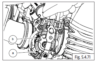
- Route throttle cable inner in throttle rotor and position throttle cable end (a) in eyelet in throttle rotor (b) correctly.
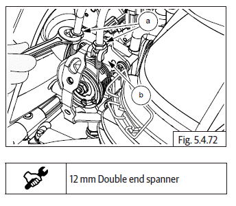
- Assemble outer lock nut (a) on adjuster in throttle body (b).
- Adjust throttle cable free play as specified and tighten 2 Nos. lock nuts on throttle cable adjuster against bracket.
- Repeat same procedure for return cable.
Throttle Body Covers on LH and RH
- Locate throttle body covers on both LH and RH of throttle body.
- Insert and tighten 2 Nos. Hex socket head bolts (M5) (a) into RH throttle body cover (b).
See also:
 Royal Enfield Interceptor 650 - Service manual > Breather Hose Connection
Breather Hose Connection to Breather Box to Air Filter Insert the shorter end of hose (b) on the tube in breather box (c). Position the clip (a) on hose correctly. Locate the other end of hose (b) on the tube in air filter box (c) and position the clip (a) over the breather hose correctly.
Royal Enfield Interceptor 650 - Service manual > Fuel Tank
Locate and slide the fuel tank into front frame guides (a). EVAP to Fuel Tank Connections Connect drain connection hose (a) to fuel tank (b). Connect the EVAP connection hose (a) to the fuel tank (b).
 Rider's Manual BMW R 1250 GS GSA
 Owner's Manual Harley-Davidson Sportster XL1200X Forty-Eight
 Owner's Manual Honda CBR650R
 Service manual Honda CBR650
 Owner's Manual Honda PCX125
 Owner's Manual Kawasaki Z1000SX
 Service manual Kawasaki Z1000SX
 Owner's Manual Lexmoto Echo
 Owner's Manual Royal Enfield Interceptor 650
 Service manual Royal Enfield Interceptor 650
 Owner's Manual Yamaha MT-07