 Honda CBR650 - Service manual > Handlebar
REMOVAL (CBR650F/FA)
LEFT HANDLEBAR
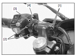
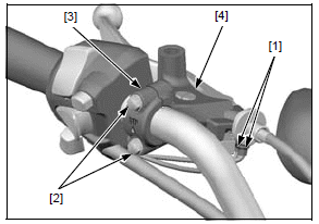
Remove the following:
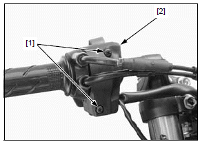
- Clutch switch connectors [1]
- Two bolts [2]
- Bracket holder [3]
- Clutch lever bracket [4]
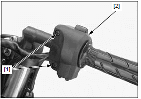
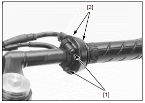
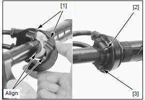
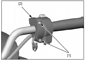
- Two screws [1]
- Left handlebar switch housings [2]
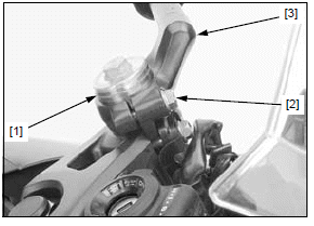
- Stopper ring [1]
- Pinch bolt [2] (loosen)
- Left handlebar [3]
RIGHT HANDLEBAR
Keep the reservoir upright to prevent air from entering the hydraulic system.
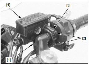
Remove the following:
- Right handlebar weight
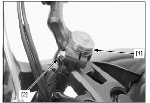
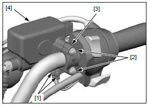
- Brake light switch connectors [1]
- Two bolts [2]
- Master cylinder holder [3]
- Front master cylinder [4]
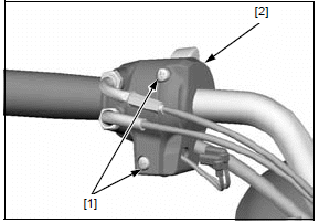
- Two screws [1]
- Upper right handlebar switch housing [2]
- Two screws [1]
- Throttle housings [2]
- Stopper ring [1]
- Pinch bolt [2] (loosen)
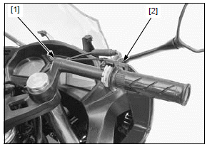
Release the right handlebar [1] from the front fork, then remove the throttle housing assembly [2] from the right handlebar.
INSTALLATION (CBR650F/FA)
LEFT HANDLEBAR
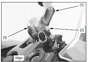
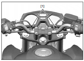
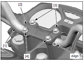
Install the left handlebar [1] over the fork tube, aligning the boss with the groove in the top bridge.
Be sure the handlebar holder is fully seated on the top bridge. Push the handlebar forward to touch the boss against the inside of the groove, then tighten the pinch bolt [2] to the specified torque.
TORQUE:27 N*m (2.8 kgf*m, 20 lbf*ft)
Install the stopper ring [3] into the groove in the fork tube.
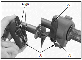
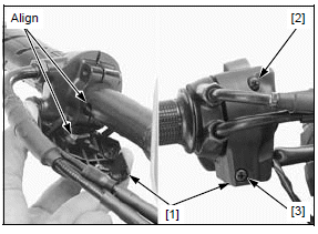
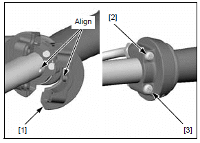
Install the left handlebar switch housings [1] by aligning the locating pin with the hole in the handlebar.
Tighten the upper screw [2] first, then tighten the lower screw [3] to the specified torque.
TORQUE:2.5 N*m (0.3 kgf*m, 1.8 lbf*ft)
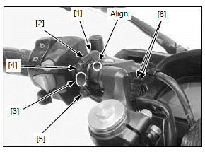
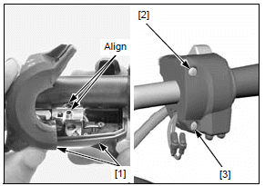
Align the edge of the bracket with the punch mark on the handlebar.
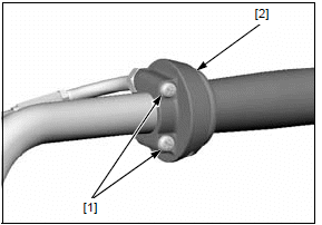
Install the clutch lever bracket [1] and holder [2] with the "UP" mark [3] facing up.
Tighten the upper bolt first [4], then the lower bolt [5].
Connect the clutch switch connectors [6].
Check the clutch lever freeplay.
RIGHT HANDLEBAR
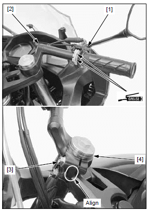
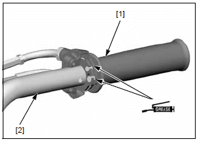
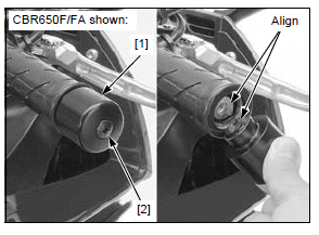
Apply grease to the cable groove and roll-up area of the throttle grip.
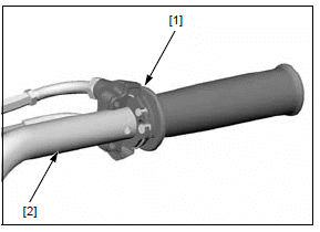
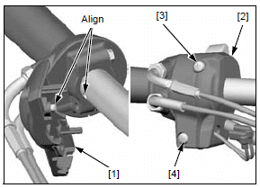
Install the throttle housing assembly [1] to the right handlebar [2].
Install the right handlebar over the fork tube, aligning the boss with the groove in the top bridge.
Be sure the handlebar holder is fully seated on the top bridge. Push the handlebar forward to touch the boss against the inside of the groove, then tighten the pinch bolt [3] to the specified torque.
TORQUE:27 N*m (2.8 kgf*m, 20 lbf*ft)
Install the stopper ring [4] into the groove in the fork tube.
Install the throttle housing [1] by aligning the locating pin with the hole in the handlebar.
Tighten the upper screw first [2], then tighten the lower screw [3] securely.
Install the right handlebar switch housings [1] by aligning the locating pin with the hole in the handlebar.
Tighten the upper screw first [2], then tighten the lower screw [3] to the specified torque.
TORQUE:2.5 N*m (0.3 kgf*m, 1.8 lbf*ft)
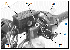
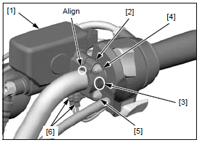
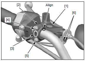
Align the edge of the master cylinder with the punch mark on the handlebar.
Install the master cylinder [1] and holder [2] with the "UP" mark [3] facing up.
Tighten the upper bolt [4] first, then the lower bolt [5] to the specified torque.
TORQUE:12 N*m (1.2 kgf*m, 9 lbf*ft)
Connect the brake light switch connectors [6].
Install the right handlebar weight.
Check the throttle grip freeplay.
REMOVAL (CB650F/FA)
Remove the following:
- Rearview mirrors
- Handlebar weights
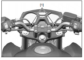
- Wire bands [1]
- Clutch switch connectors [1]
- Two bolts [2]
- Bracket holder [3]
- Clutch lever bracket [4]
- Two screws [1]
- Left handlebar switch housing [2]
Keep the reservoir upright to prevent air from entering the hydraulic system.
- Brake light switch connectors [1]
- Two bolts [2]
- Master cylinder holder [3]
- Front master cylinder [4]
- Two screws [1]
- Right handlebar switch housing [2]
- Two screws [1]
- Rear throttle housing [2]
- Four bolts [1]
- Handlebar holder [2]
- Handlebar [3]
- Throttle grip/housing assembly [1] (from the handlebar [2] )
INSTALLATION (CB650F/FA)
Apply grease to the cable groove and roll-up area of the throttle grip [1].
Install the throttle grip/housing assembly onto the handlebar [2].
Align the punch mark with the edge of the top bridge.
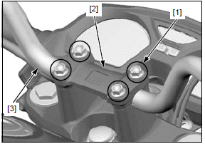
Install the handlebar [1] and holder [2]. Tighten the front bolts [3] first, then tighten the rear bolts [4] to the specified torque.
TORQUE:27 N*m (2.8 kgf*m, 20 lbf*ft)
Install the rear throttle housing [1] by aligning the locating pin with the hole in the handlebar.
Tighten the upper screw [2] first, then tighten the lower screw [3] securely.
Install the front right handlebar switch housing [1] by aligning the locating pin with the hole in the handlebar.
Install the rear right handlebar switch housing [2].
Tighten the upper screw [3] first, then tighten the lower screw [4] to the specified torque.
TORQUE:2.5 N*m (0.3 kgf*m, 1.8 lbf*ft)
Align the edge of the master cylinder with the punch mark on the handlebar.
Install the master cylinder [1] and holder [2] with the "UP" mark [3] facing up. Tighten the upper bolt [4] first, then the lower bolt [5] to the specified torque.
TORQUE:12 N*m (1.2 kgf*m, 9 lbf*ft)
Connect the brake light switch connectors [6].
Install the left handlebar switch housings [1] by aligning the locating pin with the hole in the handlebar. Tighten the upper screw [2] first, then tighten the lower screw [3] to the specified torque.
TORQUE:2.5 N*m (0.3 kgf*m, 1.8 lbf*ft)
Align the edge of the bracket with the punch mark on the handlebar.
Install the clutch lever bracket [1] and holder [2] with the "UP" mark [3] facing up. Tighten the upper bolt [4] first, then the lower bolt [5].
Connect the clutch switch connectors [6].
Secure the wires with the wire bands [1].
Install the following:
- Handlebar weights
- Rearview mirrors
Check the following:
- Clutch lever freeplay
- Throttle grip freeplay
HANDLEBAR WEIGHT REMOVAL/ INSTALLATION
Hold the handlebar weight [1] and remove the handlebar weight mounting screw [2], then remove both handlebar weights.
Install the handlebar weight to the handlebar by aligning each cutout.
Hold the handlebar weight.
Install and tighten the handlebar weight mounting screw securely.
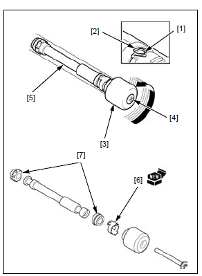
HANDLEBAR INNER WEIGHT REPLACEMENT
CBR650F/FA
Remove the left handlebar grip and throttle grip.
Straighten the retainer tab [1] with a screwdriver or punch.
Apply soapy water through the tab locking hole [2] for easy removal.
Temporarily install the handlebar weight [3] with the screw [4], aligning the flats, and then remove the inner weight [5] by turning the handlebar weight.
Remove the following from the from the inner weight:
- Screw
- Handlebar weight
- Weight retainer [6]
- Rubber cushions [7]
Install the rubber cushions and a new retainer onto the inner weight, aligning the retainer inner tabs with the cushion slit.
Temporarily install the handlebar weight with the screw, aligning the flats.
Insert the weight assembly into the handlebar. Turn the handlebar weight and hook the retainer tab with the hole in the handlebar to secure the inner weight.
Remove the screw while holding the handlebar weight securely.
Install the left handlebar grip and throttle grip.
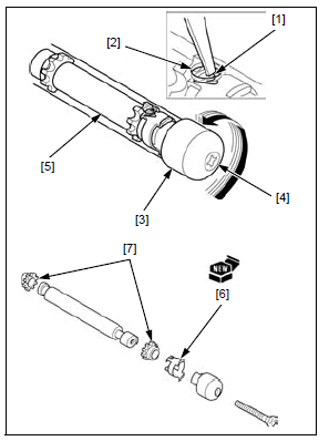
CB650F/FA
Remove the left handlebar grip and throttle grip.
Straighten the retainer tab [1] with a screwdriver or punch.
Apply soapy water through the tab locking hole [2] for easy removal.
Temporarily install the handlebar weight [3] with the screw [4], aligning the flats, and then remove the inner weight [5] by turning the handlebar weight.
Remove the following from the from the inner weight:
- Screw
- Handlebar weight
- Weight retainer [6]
- Rubber cushions [7]
Install the rubber cushions and a new retainer onto the inner weight, aligning the inner retainer tabs with the cushion slit.
Temporarily install the handlebar weight with the screw, aligning the flats.
Insert the weight assembly into the handlebar. Turn the handlebar weight and hook the retainer tab with the hole in the handlebar to secure the inner weight.
Remove the screw while holding the handlebar weight securely.
Install the left handlebar grip and throttle grip.
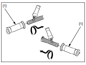
HANDLEBAR GRIP REPLECEMENT
Remove the handlebar weight.
Remove the handlebar grip [1].
Clean the inside surface of the handlebar grip and outside surface of the handlebar and throttle pipe.
Apply Honda bond A or equivalent to the inside surface of the grips and to the clean surface of the left handlebar and throttle pipe.
Allow the adhesive to dry for 1 hour before using.
Wait 3 - 5 minutes and install the grip.
Rotate the grips for even application of the adhesive.
Install the handlebar weight.
See also:
 Honda CBR650 - Service manual > Service information/troubleshooting/component location
Service information GENERAL A hoist or equivalent is required to support the motorcycle when servicing the front wheel, fork and steering stem. A contaminated brake disc or pad reduces stopping power. Discard contaminated pads and clean a contaminated disc with a high quality brake degreasing agent. Do not operate the brake lever after removing the front wheel. Use only tires marked "TUBELESS" and tubeless valves on rim marked "FOR TUBELESS". After the front wheel installation, check the brake operation by applying the brake lever. CBR650FA, CB650FA: After the front wheel installation, perform the air gap inspection. For brake system service.
Honda CBR650 - Service manual > Front wheel
REMOVAL/INSTALLATION NOTE: Do not operate the brake lever after removing the wheel. Remove the right and left front brake calipers. Remove the axle bolt [1] and loosen the right [2] and left [3] axle pinch bolts.
 Rider's Manual BMW R 1250 GS GSA
 Owner's Manual Harley-Davidson Sportster XL1200X Forty-Eight
 Owner's Manual Honda CBR650R
 Service manual Honda CBR650
 Owner's Manual Honda PCX125
 Owner's Manual Kawasaki Z1000SX
 Service manual Kawasaki Z1000SX
 Owner's Manual Lexmoto Echo
 Owner's Manual Royal Enfield Interceptor 650
 Service manual Royal Enfield Interceptor 650
 Owner's Manual Yamaha MT-07