 Royal Enfield Interceptor 650 - Service manual > Magneto Cover Sub Assembly
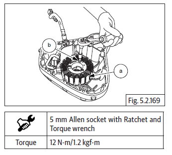
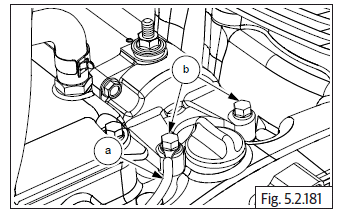
Stator coil with CPS in magneto cover
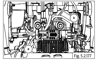
- Position stator coil (a) inside magneto cover such that
- The crank position sensor (CPS) is seated at its mounting location.
- Magneto wires and grommet are aligned to the slot on the top of the cover.
- The stator mounting holes are aligned to the mounting holes in magneto cover.
- Locate 3 Nos. Hex socket head bolts (M6) (b) in the stator coil mounting holes and tighten evenly to specified torque.
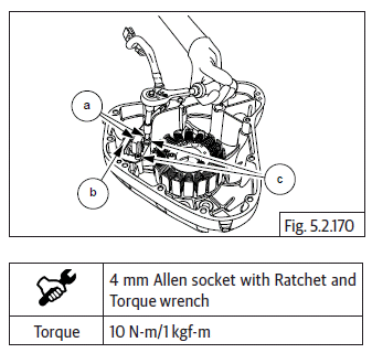
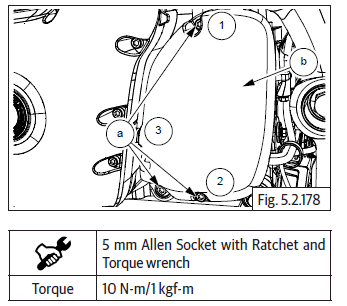
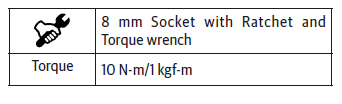
- Locate guide plate (b) over the CPS (a), ensure the mounting holes of the guide plate, CPS are aligned to the mounting holes in magneto cover.
- Locate 2 Nos. Hex socket head screws (M5) (c) on the guide plate and tighten evenly to specified torque.
Magneto Cover on Crankcase
- Locate dowel pins (a) into crankcase.
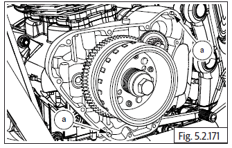
- Install Gasket (a).
- Locate magneto cover on the crankcase on LH side and ensure it is properly and fully seated.
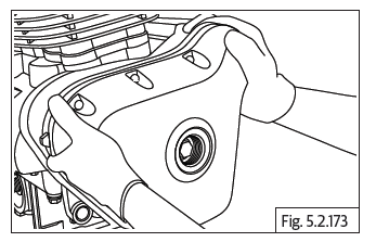
CAUTION Magnetic forces from the rotor may cause the cover to seat misaligned against crankcase.
Please ensure proper seating of the cover on the crankcase.
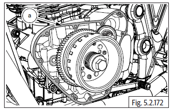
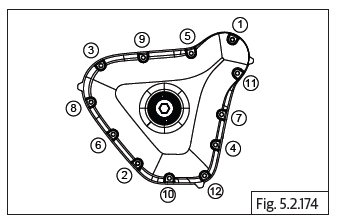
- Locate 12 Nos. Hex socket bolts (M6) on magneto cover LH cover and tighten in a crisscross pattern evenly and to specified torque.
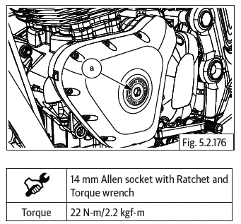
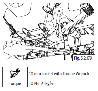
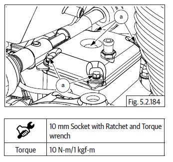
- Locate O-ring (a) on crankshaft hole plug (b).
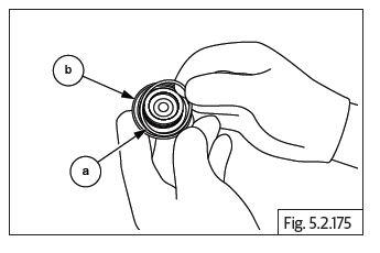
- Locate crankshaft hole plug (M34) (a) on center of magneto cover and tighten to specified torque.
Magneto / Gear position switch wiring couplers
- Connect the magneto and gear position switch wiring couplers (a) to the wiring harness on the rear side of crankcase (b).
FD Sprocket Cover
- Assemble FD sprocket cover (b) on crankcase LH.
- Locate 3 Nos. Hex socket head bolts (M6) (a) on FD sprocket cover and tighten in a crisscross pattern to specified torque.
Gear Shift Linkage
- Assemble gear shift lever (a) on shaft such that the pedal is parallel to LH foot rest.
- Locate flange Hex bolt (M6) (b) on gear shift lever and tighten to specified torque.
Starter Motor
NOTE
- Do not tap on the starter motor. It may damage the internal parts.
- Inspect the starter drive shaft teeth for any wear-out OR damages.
- Locate starter motor (a) into the housing (b) on upper crankcase LH.
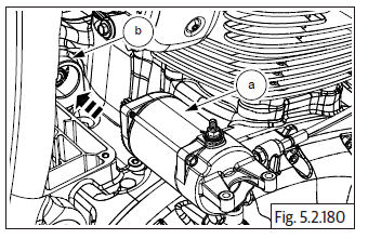
- Position negative (-ve) cable (a) eyelet over starter motor rear mounting hole and locate 1 No. Hex head flange bolt (M5) (b) sufficiently.
- Locate 1 No. Hex head flange bolt (M5) (a) on the forward mounting hole on starter motor.
- Tighten both bolts to specified torque.
Starter Motor Connections
- Connect starter motor positive (+ve) cable (a) to starter motor terminal and tighten with Hex nut (M6) (b) firmly such that the terminal is not loose. DO NOT OVERTIGHTEN.
- Slide protective cap over terminal on starter motor (c).
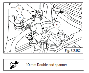
Breather Box
- Locate new gasket (a) on breather box cover (b) and assemble breather box cover on engine.
- Install and tighten 5 Nos. Hex-head flange bolts (M6) (a) to specified torque.
Breather Hose Connections
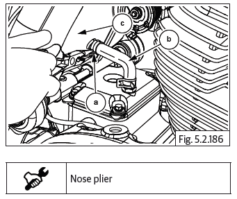
- Insert the shorter end of hose (b) on the tube in breather box (c).
- Position the clip (a) on hose correctly.
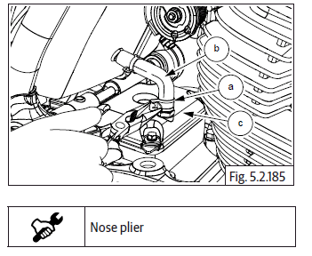
- Locate the other end of hose (b) on the tube in air filter box (c) and position the clip (a) over the breather hose correctly.
Engine Oil Filling
NOTE
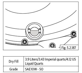
- Fill engine oil to the recommended level.
CAUTION Do not over fill engine oil has it will lead to oil coming into breather box, possible smoke through exhaust AND/OR oil leaks from joint faces.
Do not under fill engine oil as it will cause excessive heat, increased engine noise, starvation of lubrication AND/OR engine seizure.
- Fill recommended engine oil till the level is between the "Max and Min" marks on the oil level window on clutch cover.
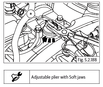
- Assemble oil filler cap (a) on the filler hole on the crankcase top on RH side and tighten just sufficiently.
- Use an adjustable plier with soft jaws. DO NOT OVERTIGHTEN.
See also:
 Royal Enfield Interceptor 650 - Service manual > Clutch Cover
Ensure the dowel pins (a) are seated properly on the upper and lower crankcases on RH side. Install gasket (a) on the crankcase if necessary smear engine oil and ensure it is properly seated on dowels. Do not use any sealant OR adhesive. Ensure racks on the clutch pull rod is facing towards the rear of the engine. Hold the clutch cover (a) in position, rotate the clutch actuating shaft to ensure it is engaged correctly with the pull rod and gently tap cover inside, till it seats fully on the dowels and crankcase. Locate 14 Nos. Hex socket bolts (M6) (a) on clutch cover and tighten them in crisscross pattern. Tighten bolts (M6) (a) evenly to specified torque.
Royal Enfield Interceptor 650 - Service manual > Engine Removal from Main Frame
Engine Removal from Main Frame Cradle Frame Removal from Engine
 Rider's Manual BMW R 1250 GS GSA
 Owner's Manual Harley-Davidson Sportster XL1200X Forty-Eight
 Owner's Manual Honda CBR650R
 Service manual Honda CBR650
 Owner's Manual Honda PCX125
 Owner's Manual Kawasaki Z1000SX
 Service manual Kawasaki Z1000SX
 Owner's Manual Lexmoto Echo
 Owner's Manual Royal Enfield Interceptor 650
 Service manual Royal Enfield Interceptor 650
 Owner's Manual Yamaha MT-07