 Royal Enfield Interceptor 650 - Service manual > Clutch Cover
- Ensure the dowel pins (a) are seated properly on the upper and lower crankcases on RH side.
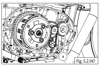
- Install gasket (a) on the crankcase if necessary smear engine oil and ensure it is properly seated on dowels. Do not use any sealant OR adhesive.
- Ensure racks on the clutch pull rod is facing towards the rear of the engine.
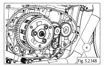
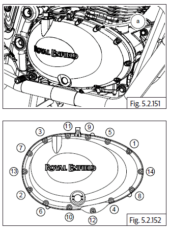
- Hold the clutch cover (a) in position, rotate the clutch actuating shaft to ensure it is engaged correctly with the pull rod and gently tap cover inside, till it seats fully on the dowels and crankcase.
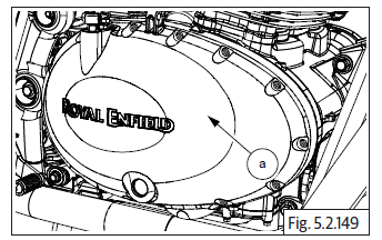
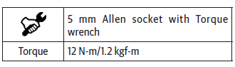
- Locate 14 Nos. Hex socket bolts (M6) (a) on clutch cover and tighten them in crisscross pattern.
- Tighten bolts (M6) (a) evenly to specified torque.
Arm Clutch Actuating Lever
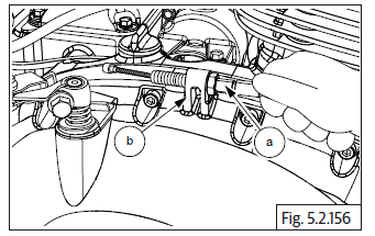
- Assemble clutch release spring (a) on shaft with the "L" bend positioned against the lug (b) in clutch cover.
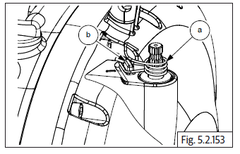
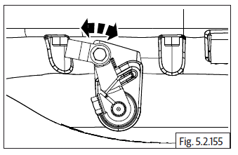
- Rotate clutch shaft (b) clockwise till it stops.
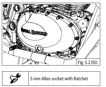
- Ensure pinch bolt is sufficiently loose, position actuating lever on shaft at 11 'O' clock position and ensure the inner side of the lever is aligned to the reference mark (a) on the clutch cover.
- Tighten pinch bolt sufficiently such that the lever is firmly clamped on the shaft.
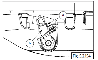
- Position the upper leg of the spring against the inside of the lever and check for proper spring action.
Clutch Cable on Clutch cover
- Assemble clutch cable assembly (a) on clutch lever (b). Refer clutch cable assembly procedure.
FD Sprocket
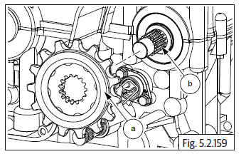
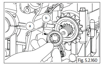
- Assemble spacer (a) on drive shaft (b) on the LH side.
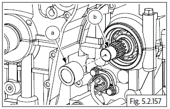
- Locate oil seal (a) on the crankcase on LH side with its open end facing inwards and tap it in gently till the outer surface of the oil seal is flush with the crankcase(b).
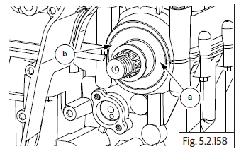
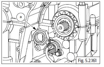
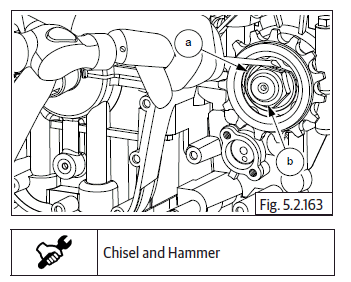
- Assemble FD sprocket (a) on drive shaft (b).
- Install new tab washer (a) on drive shaft (b).
- Assemble FD Sprocket "U'' nut (M20) (a) on drive shaft.
- Locate special tool (a) over FD sprocket and tighten nut to specified torque.
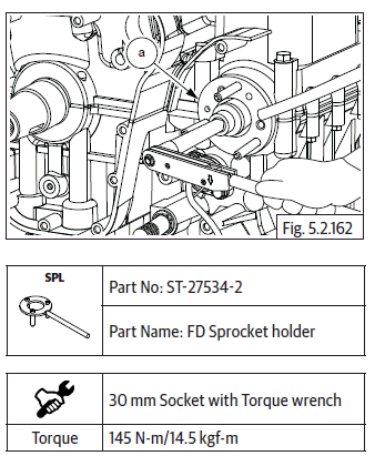
- Gently bend the tab washer (a) outer, to seat against a flat surface of the hex nut (b) with a flat chisel to prevent the nut from loosening during use.
Rear Chain to FD Sprocket
- Locate drive chain (a) over the FD sprocket teeth (b).
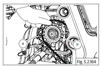
- Ensure rear chain is properly seated on the rear wheel sprocket.
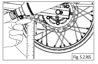
- Adjust rear chain tension as specified.
Gear Position Sensor (GPS)
- Assemble gear position sensor on the LH side of lower crankcase duly ensuring the lug (a) in the GPS is located into the hole (b) in gear selector drum.
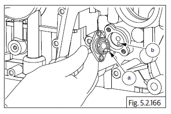
- Position cable holder (a) over the GPS.
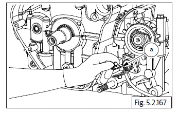
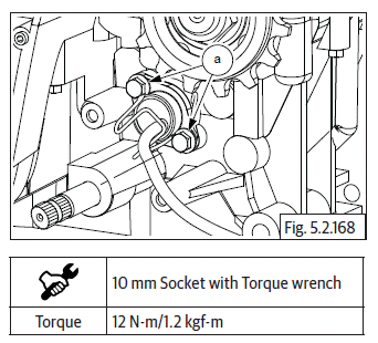
- Assemble 2 nos Hex flange head bolts (M6) (a) on the cable holder and tighten cable holder and GPS to the crankcase on the LH side to specified torque.
See also:
 Royal Enfield Interceptor 650 - Service manual > Oil Pump
Locate oil pump mounting point below crankshaft gear in RH crankcase. Assemble 4 Nos. Hex flange head bolts (M6) (a) on oil pump (b) and tighten bolts to specified torque. Locate and fit oil pump drive chain (a) on crankshaft gear (b) and sprocket on oil pump. Locate Hex flange head bolt (M6) (a) on oil pump. DO NOT TIGHTEN FULLY. Tighten the bolt to specified torque.
Royal Enfield Interceptor 650 - Service manual > Magneto Cover Sub Assembly
Stator coil with CPS in magneto cover Position stator coil (a) inside magneto cover such that The crank position sensor (CPS) is seated at its mounting location. Magneto wires and grommet are aligned to the slot on the top of the cover. The stator mounting holes are aligned to the mounting holes in magneto cover. Locate 3 Nos. Hex socket head bolts (M6) (b) in the stator coil mounting holes and tighten evenly to specified torque. Locate guide plate (b) over the CPS (a), ensure the mounting holes of the guide plate, CPS are aligned to the mounting holes in magneto cover. Locate 2 Nos. Hex socket head screws (M5) (c) on the guide plate and tighten evenly to specified torque.
 Rider's Manual BMW R 1250 GS GSA
 Owner's Manual Harley-Davidson Sportster XL1200X Forty-Eight
 Owner's Manual Honda CBR650R
 Service manual Honda CBR650
 Owner's Manual Honda PCX125
 Owner's Manual Kawasaki Z1000SX
 Service manual Kawasaki Z1000SX
 Owner's Manual Lexmoto Echo
 Owner's Manual Royal Enfield Interceptor 650
 Service manual Royal Enfield Interceptor 650
 Owner's Manual Yamaha MT-07