 Royal Enfield Interceptor 650 - Service manual > Oil Pump
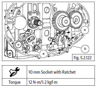
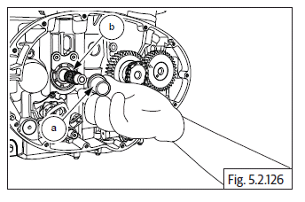
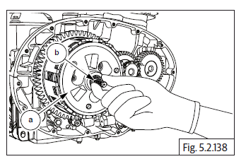
- Locate oil pump mounting point below crankshaft gear in RH crankcase.
- Assemble 4 Nos. Hex flange head bolts (M6) (a) on oil pump (b) and tighten bolts to specified torque.
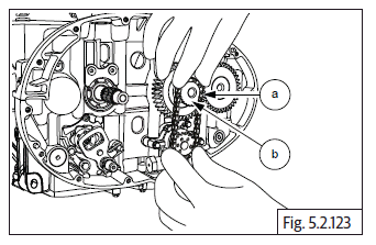
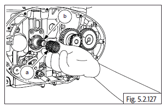
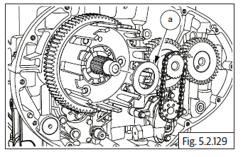
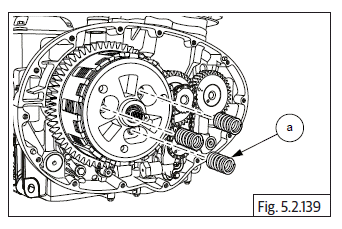
- Locate and fit oil pump drive chain (a) on crankshaft gear (b) and sprocket on oil pump.
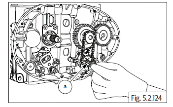
- Locate Hex flange head bolt (M6) (a) on oil pump. DO NOT TIGHTEN FULLY.
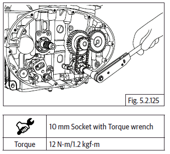
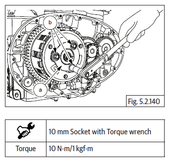
- Tighten the bolt to specified torque.
NOTE
- Lock the crank shaft by using special tool to prevent rotation while tightening bolt.
Clutch Assembly
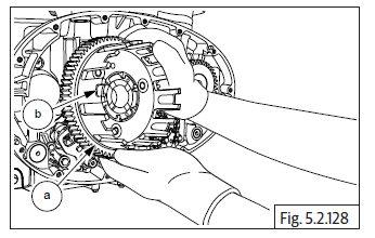
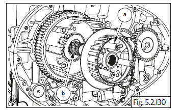
- Ensure collar on bush (a) is facing inward and assemble it on countershaft (b). Ensure it is seated properly.
- Assemble needle bearing (a) on countershaft (b).
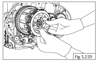
- Locate clutch housing (a) on counter shaft, with its lugs (b) facing outside.
- Ensure the clutch housing gear is correctly meshed with the gear on crankshaft.
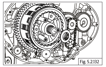
- Assemble thrust washer (a) on countershaft.
- Locate bell assembly (a) on the splines on counter shaft (b).
- Locate the anti-judder steel washer-plain, in the groove in the clutch bell.
- Assemble Belleville washer over judder washer in the clutch bell. ENSURE THE "HUMP" OF THE BELLEVILLE WASHER IS FACING INSIDE AND SEATED AGAINST THE JUDDER WASHER.
- Assemble 1 st friction plate with larger ID (less friction area) ensuring the splines of the plate are correctly positioned and located on the clutch housing.
- Assemble 1 st steel plate ensuring the splines on the plate are correctly positioned and located on the clutch bell.
- Assemble 2 nd friction plate on the clutch housing and ensure it is seated against the 1 st steel plate.
- Assemble 2 nd steel plate on clutch bell.
- Assemble 3 rd friction plate on clutch housing.
- Assemble washer (a) on countershaft.
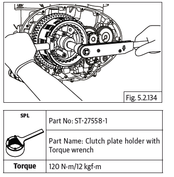
- Locate the Hex "U" nut (M17) (a).
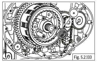
CAUTION Hex U nut is left hand thread. Turn anticlockwise to tighten nut on shaft.
- Locate and hold special tool on clutch assembly and tighten clutch hub nut to specified torque.
- Remove special tool and further assemble the following
- 3 rd steel plate on clutch bell.
- 4 th Friction plate on clutch housing.
- 4 th steel plate on clutch bell.
- 5 th Friction plate on clutch housing.
- 5 th steel plate on clutch bell.
- Locate 6 th friction plate (a) with larger ID (less friction area) on clutch hub (b) and ensure it is seated properly against the inner face of the clutch hub.
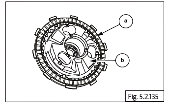
- Locate 6 th steel plate (a) on the splines in clutch hub (b) and ensure it is properly seated against the 6 th friction plate.
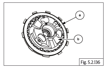
- Locate 7 th friction plate (a) with larger ID (less friction area) on clutch hub (b) such that its lugs are offset and between 2 lugs of the 6 th friction plate.
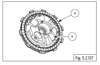
- Locate clutch hub (a) into clutch bell duly ensuring the following
- Insert pull rod (b) into clutch housing from the inside, such that the serrations on the pull rod are facing outside.
- Ensure pull rod is fully and properly seated against the bearing on the inside.
- The outer lugs of 7 th friction plate are correctly located in the INNER slots of the clutch housing.
- The outer lugs of 6 th friction plate are correctly located in the OUTER slots of the clutch housing.
- The 3 lugs of the clutch hub are correctly positioned between the 3 slots in the clutch bell (Gently rotate clutch hub back and forth, to match the slots of the clutch bell).
- The three mounting studs of the clutch bell are central to the slots in the clutch hub.
- Insert 3 Nos. compression springs (a) in hub.
- Locate pressure plate (a) on clutch hub with the words "OUT" and "FR" facing outside.
- Assemble 3 Nos. Hex bolts (M6) (b) and tighten pressure to clutch hub, sequentially to specified torque.
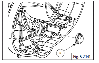
Oil Level Window on Clutch Cover
- Locate new oil window (a) on clutch cover with the window facing towards clutch cover outer and gently press till it is seated fully inside.
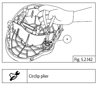
- Assemble circlip (a) in the groove in clutch cover and ensure it is correctly locked in the clutch cover.
Clutch Actuating Lever Assembly
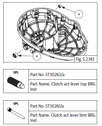
- Ensure needle bearings (a) are assembled in the clutch cover.
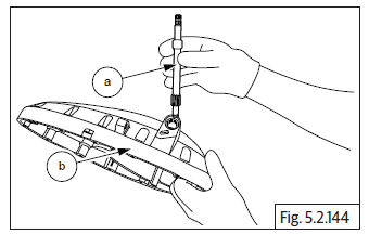
- Insert clutch actuating shaft (a) into clutch cover (b) with the gear facing inside and the splines facing outside.
- Assemble washer (b) on the shaft bottom inside the clutch cover.
- Assemble E-clip (a) in the slot in shaft bottom inside clutch cover.

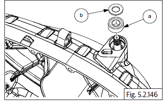
- Assemble oil seal (a) in clutch cover at the top with the lips facing down.
- Assemble washer (b) above oil seal.
See also:
 Royal Enfield Interceptor 650 - Service manual > Injector, TPS, MAPS, ISC Connections
Injector, Throttle Position Sensor (TPS), Manifold Absolute Pressure (MAP) Sensor and Idle Speed Controller (ISC) Connections Connect the LH and RH injector connectors (a) located on throttle body (b). Connect TPS connector (a) to sensor (b) at bottom of throttle body. Connect idle speed sensor connector (a) on throttle body (b). Connect purge valve hoses (a) to the inlet pipes on the top of the throttle body.
Royal Enfield Interceptor 650 - Service manual > Clutch Cover
Ensure the dowel pins (a) are seated properly on the upper and lower crankcases on RH side. Install gasket (a) on the crankcase if necessary smear engine oil and ensure it is properly seated on dowels. Do not use any sealant OR adhesive. Ensure racks on the clutch pull rod is facing towards the rear of the engine. Hold the clutch cover (a) in position, rotate the clutch actuating shaft to ensure it is engaged correctly with the pull rod and gently tap cover inside, till it seats fully on the dowels and crankcase. Locate 14 Nos. Hex socket bolts (M6) (a) on clutch cover and tighten them in crisscross pattern. Tighten bolts (M6) (a) evenly to specified torque.
 Rider's Manual BMW R 1250 GS GSA
 Owner's Manual Harley-Davidson Sportster XL1200X Forty-Eight
 Owner's Manual Honda CBR650R
 Service manual Honda CBR650
 Owner's Manual Honda PCX125
 Owner's Manual Kawasaki Z1000SX
 Service manual Kawasaki Z1000SX
 Owner's Manual Lexmoto Echo
 Owner's Manual Royal Enfield Interceptor 650
 Service manual Royal Enfield Interceptor 650
 Owner's Manual Yamaha MT-07